
Choosing a Mining Drilling Jumbo: Face Size, Boom Reach and Ground Conditions





Selecting a drilling jumbo starts with more than matching machine size to tunnel dimensions. Face coverage, maneuvering clearance, rock conditions and support requirements all affect suitability.
For technical evaluators, the strongest candidate is the machine that can drill the required pattern accurately and repeatedly while fitting the complete development cycle.
This guide examines Drilling Jumbos for mining operations, from boom reach and ground conditions to support compatibility, equipment utilization and the evidence needed for procurement.
Start With the Face and the Required Drill Pattern

A jumbo’s nominal coverage area is a useful screening figure, but it does not establish whether the machine can drill every required hole efficiently.
Obtain scaled drawings of the smallest and largest planned development profiles, including arched backs, irregular corners, overbreak allowances and any restrictions imposed by installed services.
Overlay the proposed blast pattern on each profile. Include cut holes, lifters, perimeter holes and any probe or relief holes required by the mining method.
Ask the supplier to show achievable hole collars and feed orientations from a realistic setup position. Coverage should include both position and drilling angle.
Pay particular attention to lifters near the floor and perimeter holes near the back and shoulders. These locations often expose limitations hidden by headline coverage figures.
A boom may reach a collar point yet lack clearance to align the feed. Check feed length, articulation, drill steel handling and interference with adjacent surfaces.
Evaluate the expected number of carrier setups per face. Repositioning can extend the cycle and introduce alignment error, especially where accurate perimeter control is important.
For variable headings, compare the machine against the actual production mix rather than one representative profile. A good fit for a large access drive may be inefficient elsewhere.
How Many Booms Does the Development Plan Need?
Single-boom jumbos suit many smaller headings where space, purchase cost and maneuverability constrain selection. Their output depends on hole count, drilling rate and operating discipline.
Two-boom machines can drill simultaneously and may shorten face time where the heading provides enough space. Actual gains depend on boom interference and operator coordination.
Larger multi-boom configurations may suit broad faces and intensive development schedules, but their value falls if simultaneous drilling is restricted by geometry or downstream bottlenecks.
Compare alternatives using a complete cycle model, not the number of booms alone. Include positioning, drilling, charging, blasting, ventilation, scaling, mucking and ground support.
For example, a second boom has limited schedule value if the loader cannot clear the face promptly or crews cannot install support before the next round.
Model effective simultaneous drilling time explicitly. Allow for setup, feed movement, steel changes, operator delays and periods when booms cannot safely work alongside each other.
Can the Carrier Reach and Operate at the Face?
A jumbo must travel through the mine as well as operate at the face. Check transport width, height, turning envelope, axle loads and machine weight.
Map the route from workshop to heading, including ramps, intersections, doors, passing bays, sumps and cable infrastructure. Compare actual constraints with the supplier’s swept-path drawings.
Check gradients and traction against the mine’s wet, muddy or uneven road conditions. Manufacturer ratings should be reviewed for the relevant machine configuration and operating environment.
At the face, allow room for stabilizers, safe access, hose routing and maintenance. Confirm whether the carrier can be positioned without obstructing ventilation or other equipment.
Look beyond the current development plan. Future headings, haulage changes and installed infrastructure can turn a machine that fits today into a difficult asset to deploy.
Match the Drilling System to the Ground
Rock hardness matters, but compressive strength alone cannot predict performance. Abrasivity, fractures, stress, groundwater and rock variability also affect penetration, consumables and hole stability.
Provide suppliers with representative geological data and production records. Include rock type, strength ranges, abrasivity results where available, structural features and known zones of difficult drilling.
In hard, abrasive rock, assess rock drill power alongside expected bit life, rod consumption and maintenance requirements. Faster penetration is valuable only if total cycle performance improves.
In fractured ground, hole deviation, bit jamming and collapsing holes may dominate. Ask how feed control, flushing and operating procedures address these conditions.
Water-bearing ground can complicate flushing, visibility and hole stability. Review water supply quality, drainage, sealing requirements and procedures for sudden changes in inflow.
High-stress or burst-prone areas require site-specific geotechnical controls. Equipment selection should follow the mine’s ground-control plan and the direction of qualified geotechnical personnel.
Request comparable operating references, but examine their limits. A similar machine in another mine is useful evidence only when rock, hole sizes and working practices are comparable.
Check Hole Accuracy, Automation and Operator Control
Accurate collaring, alignment and depth control support predictable blasting and can reduce the need for corrective work. Results depend on equipment, calibration and operator practices.
Compare manual, assisted and automated functions against the site’s actual needs. Relevant features may include positioning assistance, anti-jamming control, automatic drilling cycles and drill-plan guidance.
Ask how the system establishes machine position and orientation underground. Confirm survey requirements, reference-point availability and the process for checking alignment before drilling starts.
For each proposed control system, request documented accuracy under stated conditions. Distinguish machine positioning accuracy from achieved hole deviation within the rock.
Drill-plan software should exchange data with the mine’s design workflow. Verify file formats, version control, network requirements and whether plans remain available during connectivity outages.
Digital logs can reveal drilling time, interruptions and unusual responses. Treat these records as operational evidence that needs interpretation, rather than a direct geological measurement.
Include operator training and calibration in the comparison. Advanced functions deliver less value when crews cannot use them consistently or when sensors are poorly maintained.
Will Ground Support Fit the Same Development Cycle?
Blast-hole drilling and ground support are related but distinct tasks. Determine whether support will be installed by a dedicated bolter, a multipurpose machine or another method.
If a jumbo is expected to perform support work, verify the exact attachments and approved functions. A blast-hole boom does not automatically provide a complete bolting system.
Check bolt length, hole orientation, installation height, resin or grout requirements and access to the back and shoulders. Include mesh handling where the support design requires it.
Compare the time and equipment movements for each support arrangement. A multipurpose machine may reduce transfers, while a dedicated bolter may allow better scheduling across headings.
Confirm separation distances, exclusion zones and the sequence for scaling and support installation. These requirements must follow the mine’s procedures and applicable regulations.
Compare Power, Utilities and Underground Compatibility
Most face-drilling jumbos require electrical power for drilling and hydraulics, while travel arrangements vary by model. Confirm the power sources for every operating mode.
Check supply voltage, frequency, available capacity, protection settings and connector standards. Include cable length, handling, storage and the practical route to each working face.
Confirm water pressure, flow and filtration requirements for flushing. Assess how interruptions, poor water quality or limited drainage could affect drilling and equipment reliability.
Where battery-electric or other low-emission travel is offered, evaluate charging infrastructure, duty cycle and recovery arrangements. An electric drilling mode alone does not establish zero-emission travel.
Review ventilation requirements for the entire operating cycle, including any diesel-powered travel and blasting activities. The mine’s ventilation design remains the controlling basis for operation.
Check compatibility with communication networks, maintenance systems and site cybersecurity requirements. These details matter when remote diagnostics or software updates depend on external connections.
Build a Cost Comparison Around Productive Metres
Purchase price is only one part of the decision. Compare alternatives over the expected operating life using the same production assumptions and cost boundaries.
Include energy, drill steel, bits, hydraulic components, planned servicing, labour, training and major rebuilds. Add the cost of infrastructure changes required by each option.
Estimate productive development metres using achievable round length, advance per blast and completed cycles. Separate scheduled availability from the time the machine is actually drilling.
Use a consistent measure such as total relevant cost per completed development metre. State whether support, blasting and downstream delays are included to avoid misleading comparisons.
Run sensitivity cases for penetration rate, consumable life, availability and utilization. A machine that wins only under optimistic assumptions deserves closer technical and commercial review.
Consider the cost of lost development time where it affects mine access or production. Use a site-approved value and avoid counting the same delay twice.
Service capability can materially change lifecycle cost. Check local parts availability, field support response, diagnostic access and the mine’s ability to perform routine repairs independently.
What Evidence Should Suppliers Provide?
Issue a common technical package so suppliers respond to the same profiles, geology, drill patterns, utilities and production targets. Record assumptions wherever site data is incomplete.
Request dimensioned coverage plots, turning data, equipment weights, utility requirements and maintenance access drawings. Require configurations to match the quoted machine and attachments.
Ask for a cycle-time estimate that identifies drilling rates, repositioning, simultaneous boom use and exclusions. Challenge any assumptions that differ from measured site performance.
Obtain maintenance schedules, recommended spares, component life assumptions and training plans. Check warranty terms alongside the conditions required to maintain coverage.
Where practical, arrange a site trial or reference visit with agreed measurements. Track completed holes, achieved advance, delays, consumables and operator feedback across representative conditions.
If a trial is unavailable, use conservative scenarios and define acceptance criteria before purchase. Clarify how coverage, functionality and performance will be verified after commissioning.
Make the Final Selection
The right jumbo is the one that covers the required patterns, reaches the face safely and supports the planned development rate under credible ground conditions.
Use face geometry and carrier access to eliminate unsuitable machines first. Then compare drilling performance, support interfaces, utilities, service capability and cost per completed metre.
Document uncertainties and test the assumptions that drive the decision. This gives evaluators a defensible basis for choosing equipment that can perform throughout the mine’s development plan.
Related News
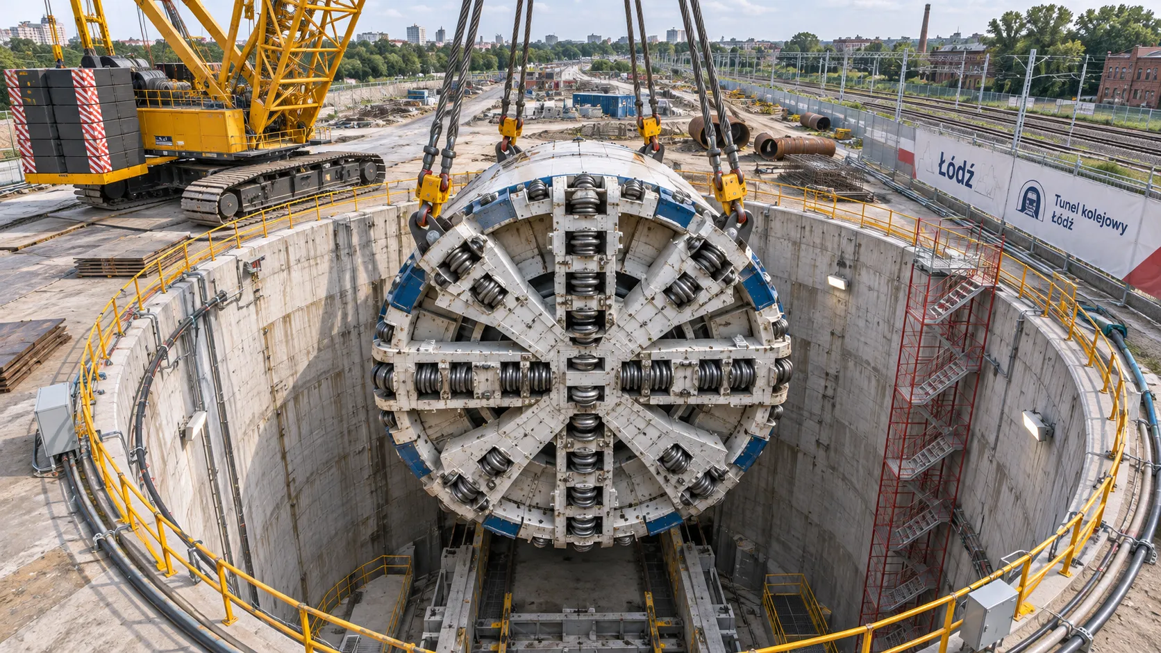
Hampton Roads TBM Cutterhead Lowered into Łódź Rail Tunnel Shaft
Hampton Roads TBM cutterhead is lowered into a Łódź rail tunnel shaft. Explore the machine’s journey from Virginia and its next tunnelling assignment.
China's TBM Export Controls Prompt Infrastructure Concerns in India
China's TBM export controls could affect infrastructure projects in India. Explore potential supply risks and practical procurement steps.
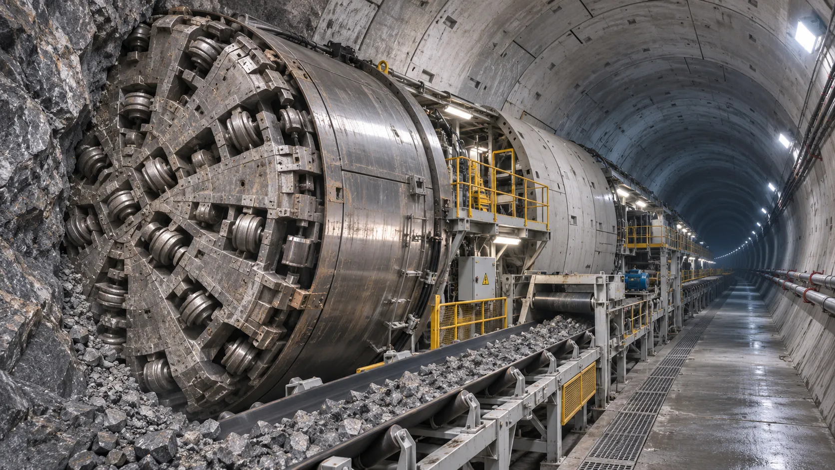
How TBM Excavation Works in Rock and Soft Ground: A Practical Guide
TBM Excavation in rock and soft ground explained: compare machine types, ground support, spoil removal, and the factors that guide smarter project planning.
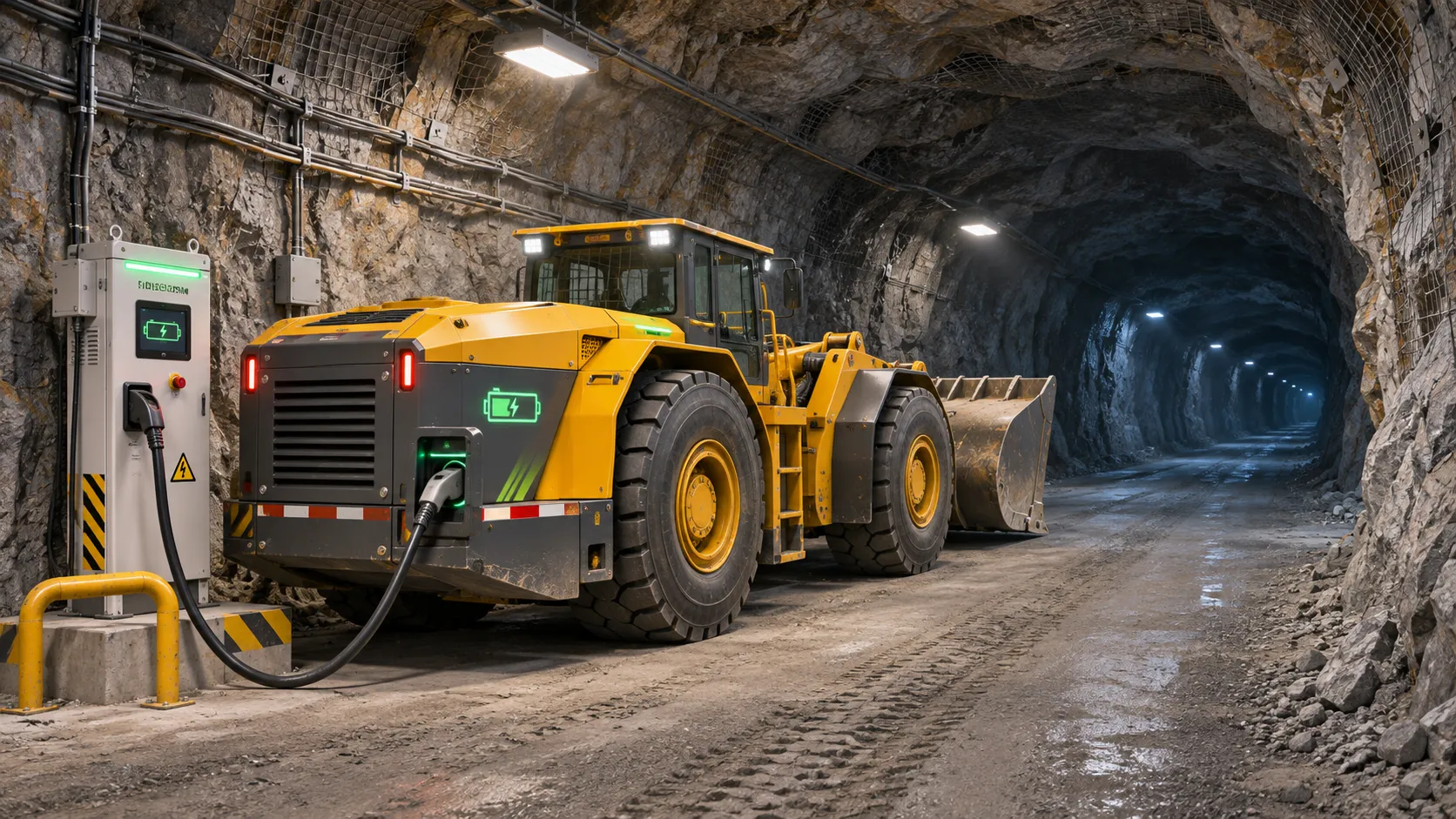
Choosing a Zero-Emission Underground Equipment Supplier: What to Check
Choosing a zero emission underground equipment supplier? Compare duty-cycle performance, charging, safety, total costs and support before you commit.
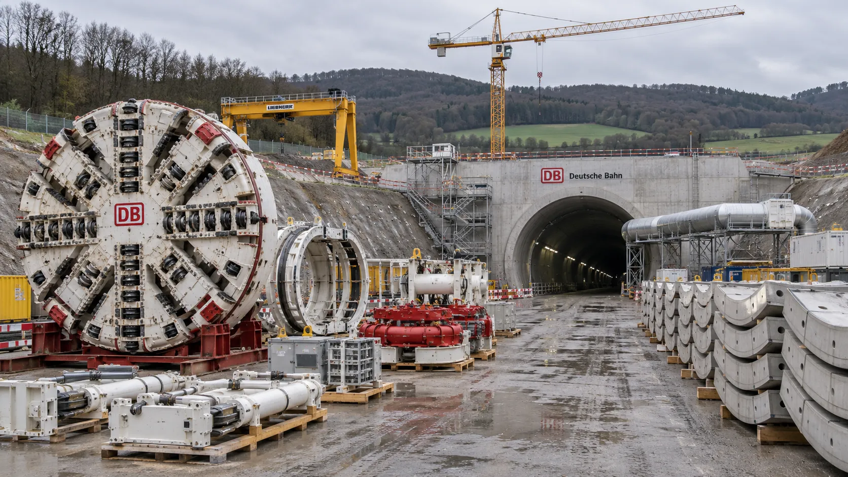
Construction Starts on Germany's Pfaffensteig Rail Tunnel, With Two TBMs Planned
Pfaffensteig rail tunnel construction is underway in Germany. Discover how two planned TBMs will support the 11-kilometre project near Stuttgart.
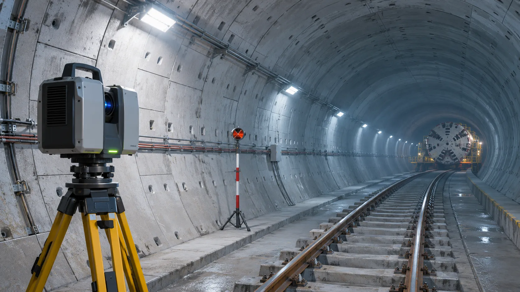
How Real-Time Underground Mapping Systems Work in Tunneling
Discover how real-time underground mapping systems guide tunneling teams, integrate sensor data, and support confident decisions with verified accuracy.
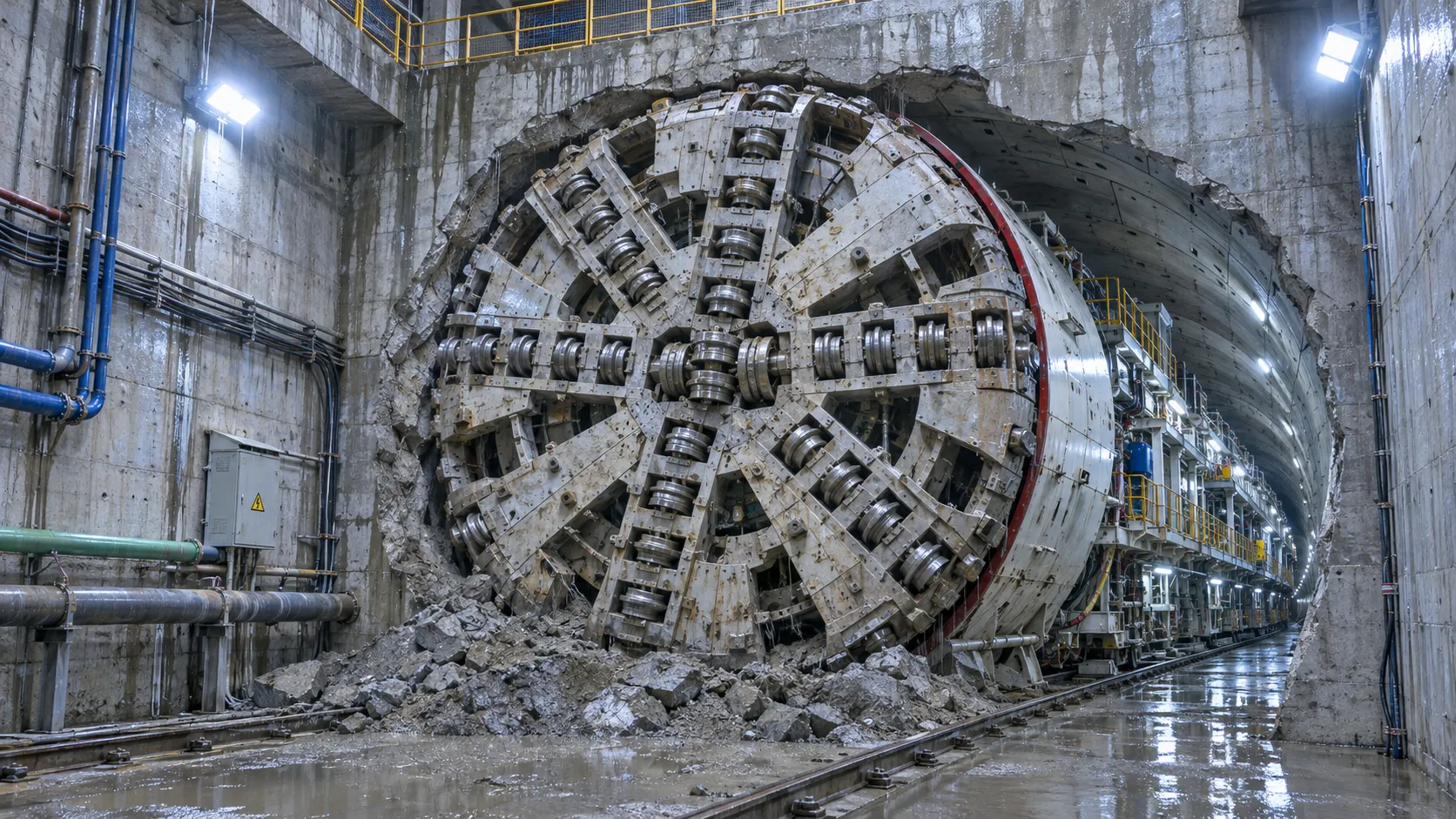
First Mechanized Tunnel Crossing Beneath the Panama Canal Completed
Panama Canal tunnel crossing: Explore the reported Metro Line 3 milestone and what it could mean for future underwater tunneling projects.
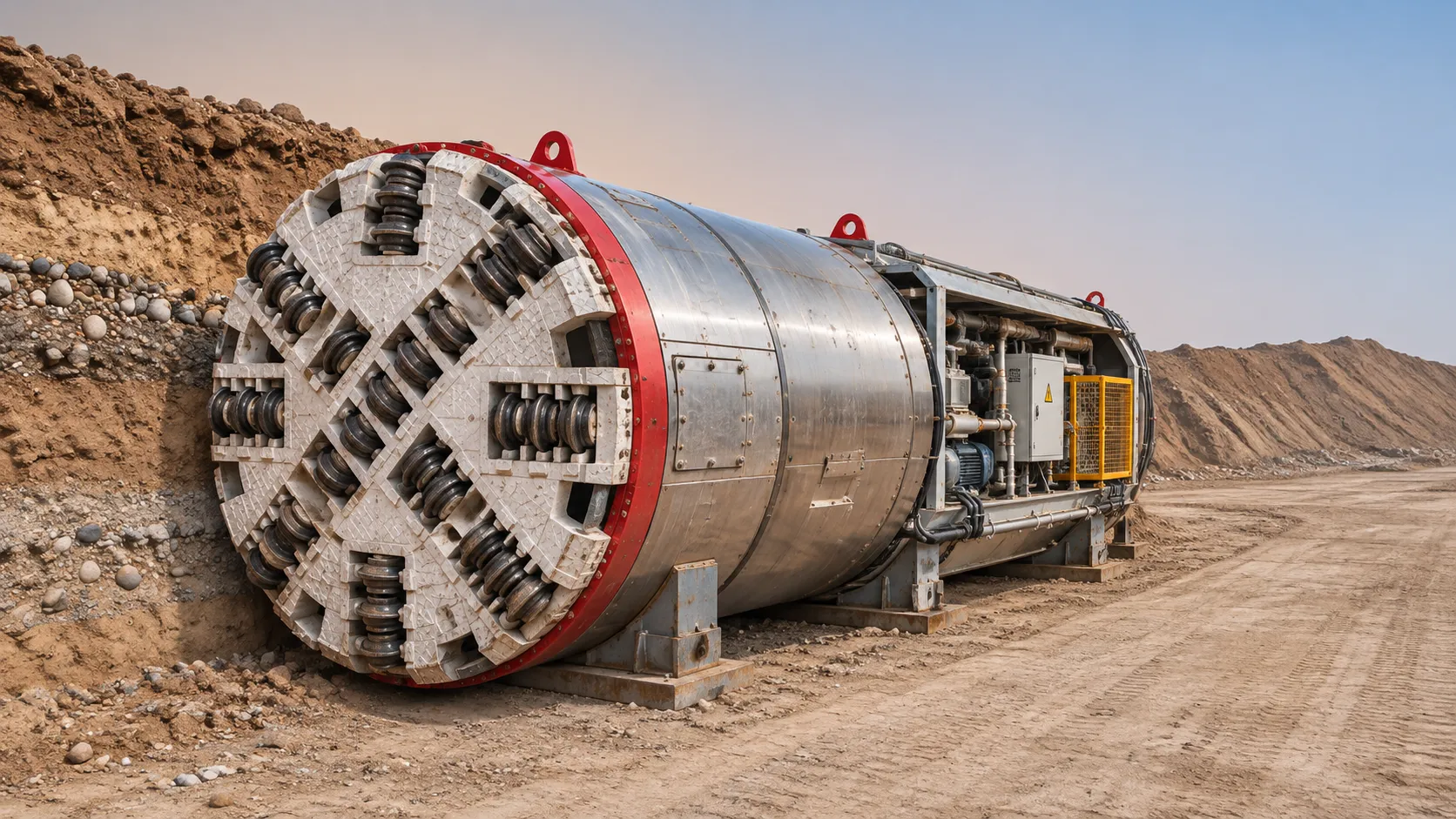
Underground Utility Construction Equipment: Choosing by Ground Conditions
Choose underground utility construction equipment with confidence. Compare trenching, HDD, microtunnelling and TBMs by ground conditions, risk and cost.
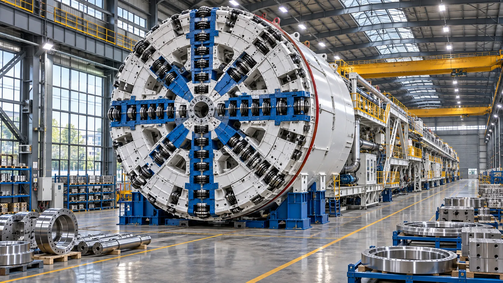
China Sets Tunnel Boring Machine Export Controls as India Pushes Local Production
China tunnel boring machine export controls could reshape procurement as India pushes local production. Explore potential supply and project impacts.
Related News
- 00
0000-00
Hampton Roads TBM Cutterhead Lowered into Łódź Rail Tunnel Shaft - 00
0000-00
Choosing a Mining Drilling Jumbo: Face Size, Boom Reach and Ground Conditions - 00
0000-00
China's TBM Export Controls Prompt Infrastructure Concerns in India - 00
0000-00
How TBM Excavation Works in Rock and Soft Ground: A Practical Guide - 00
0000-00
Choosing a Zero-Emission Underground Equipment Supplier: What to Check
Weekly Insights
Stay ahead with our curated technology reports delivered every Monday.