
Underground Rock Drilling Rig Selection: Matching Drill Coverage to Tunnel Size





An underground rock drilling rig fits a tunnel only when it can drill the required blast-hole pattern from a workable setup position, with clearance for the carrier, feeds, and moving booms. A published coverage area is useful for screening candidates, but it cannot establish that fit on its own. Two rigs with similar nominal coverage can differ in their ability to reach the crown, place lifter holes, or hold the feed at the angle required for perimeter drilling.
For technical evaluation, the strongest starting point is a comparison between the planned drilling pattern and the rig’s usable drilling envelope in the actual tunnel profile. Favor a configuration that covers routine rounds with manageable positioning demands and acceptable drilling accuracy. A larger machine becomes worthwhile when its additional reach or drilling capacity improves the excavation cycle enough to justify its access, clearance, and service requirements.
Compare the drilling pattern with the actual face geometry
Tunnel width and height provide the first screening dimensions. Cross-sectional area alone provides too little information. A narrow, high heading and a wide, low heading can have similar areas while demanding different boom movements. Arched crowns, vertical sidewalls, flat floors, and irregular shoulders each create different reach constraints.
Begin with the designed excavation profile, then account for the conditions in which the jumbo will stand. Installed support, ventilation ducting, pipes, cables, drainage arrangements, and uneven ground can restrict its operating space. The rig may have adequate reach against an unobstructed design outline yet lose a useful setup position once these features are included.
The blast-hole layout adds another layer. Reaching a collar location—the point where a hole enters the face—is only part of the requirement. The feed must also align with the intended drilling direction. Perimeter holes may need outward inclination, while cut holes have their own positional and angular demands. A rig that touches every point on a face drawing may still struggle to execute the complete pattern.
Prepare an overlay showing the face profile, hole collars, and drilling directions. Examine the crown, shoulders, sidewall limits, and floor-level holes separately. These boundary locations can expose restrictions that remain hidden when coverage is presented as a single area figure.

The overlay should use a defined carrier position and orientation. A coverage drawing based on a centered, level machine may be misleading where the available standing area forces an offset setup. On a gradient or uneven floor, changes in chassis attitude can also affect the relationship between the boom workspace and the face. Ask for these conditions to be represented in the assessment.
Establish what the quoted drilling coverage includes
A coverage figure needs a clear definition before it can support a comparison. Request the coverage diagram for the proposed boom, feed, and carrier configuration, together with its reference conditions. Establish the assumed distance from the face, setup height, carrier position, and feed orientation. Also distinguish between the combined reach of all booms and the area each boom can serve independently.
The distinction matters because a boundary drawn around all reachable positions says little about how easily the rig works inside it. Near an envelope limit, the boom may have fewer available orientations, the feed may approach surrounding rock, or another boom may occupy the necessary space. Useful coverage therefore depends on both reach and the movements required to drill and withdraw safely.
A technical review should resolve several specific questions:
- Can the feed reach the critical collars at the required angles? Check drilling alignment, including any required lookout angle, rather than collar access alone.
- Can the full feed assembly move through the required path? Include the drill, hoses, supports, and other fitted equipment in the clearance assessment.
- Can the rig collar and retract at the profile boundaries? A static drilling pose does not demonstrate that the feed can enter and leave that position.
- What changes when the other booms are working? Establish which parts of the pattern remain available during simultaneous operation.
- Which holes require carrier movement? Identify their locations and the positioning sequence needed to complete them.
Clearance allowances should reflect the uncertainty of the excavation and the machine’s operating requirements. There is no useful universal margin that can replace this assessment. A tightly controlled profile with a prepared floor presents different conditions from a heading with variable overbreak, uneven ground, and changing service positions. The evaluator should document the allowance used and the reason for it.
Pay particular attention to low holes and upper corners. Lifter-hole access can be limited by the chassis, feed geometry, or floor conditions. At the crown and shoulders, reach may be available only with restricted feed orientation. These are precisely the locations where an attractive nominal coverage figure needs closer examination.
Choose boom count and feed length around the working cycle
Boom count affects both face coverage and the opportunity to drill holes in parallel. A single-boom jumbo may suit a smaller heading where the pattern is accessible from one setup and drilling time meets the production requirement. Additional booms can improve capacity on larger faces, provided each has enough useful work space and enough assigned holes to remain productive.
More booms do not create a proportional reduction in drilling time. Their working zones can overlap, feeds can interfere, and some hole groups may impose sequencing constraints. A narrow face may leave little room for independent movement even when the carrier itself fits. Conversely, a broad face can benefit from separating drilling tasks into zones that each boom can cover efficiently.
Assess the proposed configuration using a realistic drilling sequence. Allocate the cut, production, perimeter, and lifter holes to individual booms, then examine where one boom must wait for another. The relevant comparison is the time to complete an acceptable round, including positioning, collaring, drilling, withdrawal, and any carrier movement. Total installed drilling power cannot answer that question.
Feed length creates a separate tradeoff. A longer feed can support longer drilling arrangements where the machine configuration and ground conditions permit them. It also requires more space for positioning and can become difficult to orient in a restricted profile. A shorter feed may improve maneuverability, but its suitability depends on the required hole depth and the rod-handling arrangement.
Select feed length against the planned round and the available working space together. Confirm the usable hole depth for the proposed setup, rather than inferring it directly from overall feed length. Where extension drilling is proposed, include rod changes, handling space, and the effect on cycle time. Those details can change the comparison between an apparently compact solution and a larger rig.
Longer holes also require attention to trajectory control. Collar accuracy, feed alignment, rod behavior, and rock structure all influence where the hole finishes. An orientation error has a greater positional effect as drilling distance increases. For selection purposes, establish whether the proposed combination of feed, drilling equipment, and control system can support the project’s hole-position and direction requirements under the expected conditions.
Digital navigation and automated positioning can assist setup and execution, but their value depends on a workable mechanical arrangement. A control system cannot extend physical reach or remove a collision between a feed and the tunnel profile. Evaluate automation after confirming that the machine can achieve the required drilling positions.
Check access and setup before accepting a coverage match
A machine that covers the face still needs to reach it, turn where required, and establish a stable working position. Review the entire route from the assembly or parking area to the heading. Transport width and height, turning geometry, articulation, gradients, and local restrictions all belong in this check.
Swept-path assessment is especially useful where the route includes tight junctions or changes in direction. A carrier may pass through a straight opening yet encounter difficulty at a bend because different parts of the machine follow different paths. Include projections and the specified travel configuration, rather than checking chassis dimensions alone.
At the face, establish how much longitudinal space the rig needs. Feed positioning, boom movement, stabilizer deployment, and the selected drilling arrangement all influence the required distance from the rock. This can affect service access and the space available behind the machine. Verify that hoses and cables can be managed through positioning and drilling without obstructing necessary movement.
Floor preparation deserves explicit treatment. Loose material, standing water, or irregular levels can affect setup repeatability and working clearance. If a candidate depends on a particular floor condition to cover the pattern, include the preparation needed to achieve it in the operating assessment. Otherwise, the equipment comparison will credit the rig with performance that the heading cannot consistently support.
Occasional repositioning may be an acceptable compromise where the alternative is a substantially larger machine. Its cost depends on frequency and difficulty. Moving once to complete an unusual widening is different from moving during every standard round to reach routine perimeter holes. Record the expected movements, their purpose, and their contribution to the cycle.
Make the final comparison against representative rounds
The most useful selection document is a coverage assessment tied to the project’s own drawings and drilling requirements. Include the normal heading, the most restrictive routine profile, and any recurring enlargement that materially affects equipment choice. An exceptional chamber may justify a separate drilling arrangement if sizing the entire fleet around it would burden everyday operation.
For each candidate underground rock drilling rig, request a configuration-specific review covering:
- The setup position, face distance, floor attitude, and access assumptions used.
- Reach and feed alignment for all critical holes, including perimeter and lifter holes.
- Boom assignments, interference constraints, and the proposed drilling sequence.
- Expected carrier movements and the holes that require them.
- Cycle-time assumptions for drilling, handling, positioning, and withdrawal.
- Clearance constraints associated with installed support and services.
Simulation or a geometric reach study can help screen alternatives, provided it represents the offered configuration and project conditions. Where the decision depends on difficult boundary positions, a representative physical demonstration can provide additional evidence. The demonstration should include the awkward collars, required angles, and movement paths that determine suitability.
Acceptance criteria should be agreed before that demonstration. Define which holes must be drilled from the primary setup, where repositioning is permitted, and what positional and angular tolerances apply. Include the assumptions behind any cycle-time comparison so that a fast result achieved under unusually favorable conditions does not become the purchasing benchmark.
The preferred machine is the one whose usable envelope and drilling sequence remain practical across the headings it will repeatedly encounter. When two candidates both meet that requirement, compare the clearance they retain at difficult positions, the movements they require during a round, and the demands they place on access and floor preparation. Those differences give technical evaluators a firmer basis for selection than nominal coverage area alone.
Related News
China's TBM Export Controls Prompt Infrastructure Concerns in India
China's TBM export controls could affect infrastructure projects in India. Explore potential supply risks and practical procurement steps.
How TBM Excavation Works in Rock and Soft Ground: A Practical Guide
TBM Excavation in rock and soft ground explained: compare machine types, ground support, spoil removal, and the factors that guide smarter project planning.
Choosing a Zero-Emission Underground Equipment Supplier: What to Check
Choosing a zero emission underground equipment supplier? Compare duty-cycle performance, charging, safety, total costs and support before you commit.
Construction Starts on Germany's Pfaffensteig Rail Tunnel, With Two TBMs Planned
Pfaffensteig rail tunnel construction is underway in Germany. Discover how two planned TBMs will support the 11-kilometre project near Stuttgart.
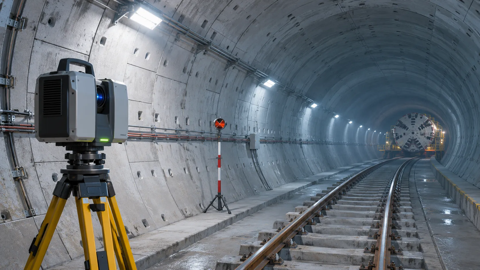
How Real-Time Underground Mapping Systems Work in Tunneling
Discover how real-time underground mapping systems guide tunneling teams, integrate sensor data, and support confident decisions with verified accuracy.
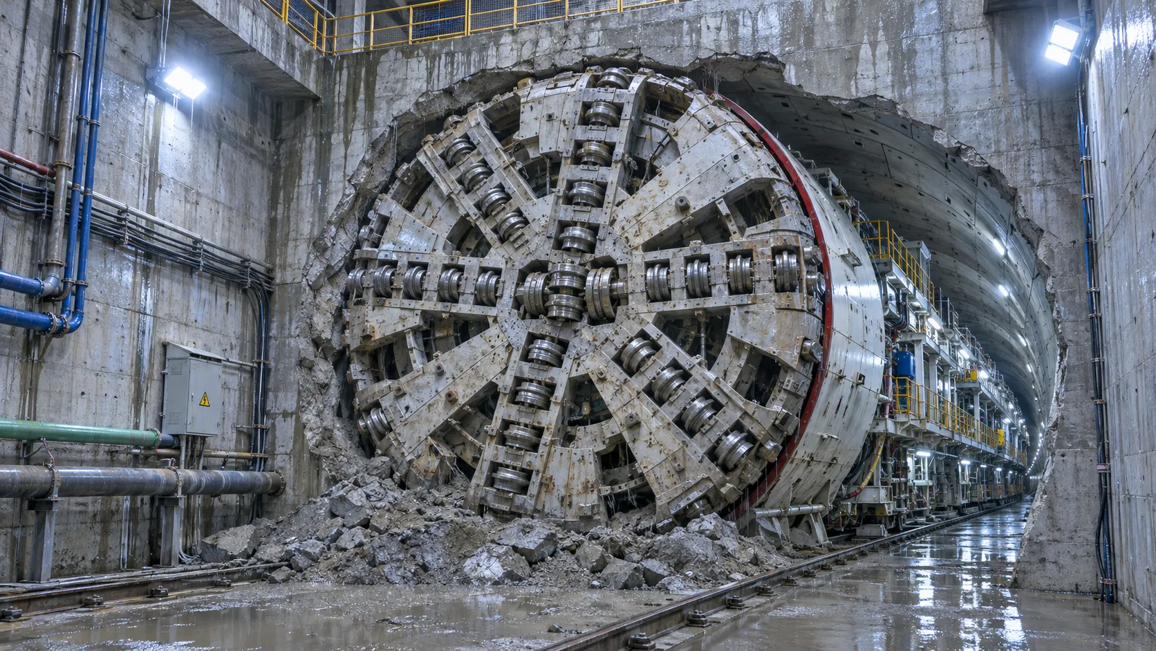
First Mechanized Tunnel Crossing Beneath the Panama Canal Completed
Panama Canal tunnel crossing: Explore the reported Metro Line 3 milestone and what it could mean for future underwater tunneling projects.
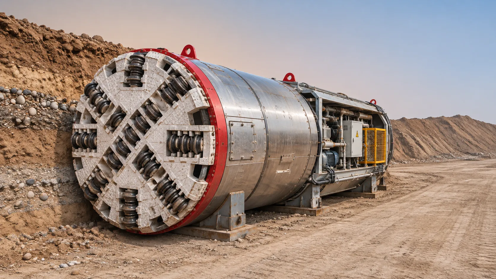
Underground Utility Construction Equipment: Choosing by Ground Conditions
Choose underground utility construction equipment with confidence. Compare trenching, HDD, microtunnelling and TBMs by ground conditions, risk and cost.
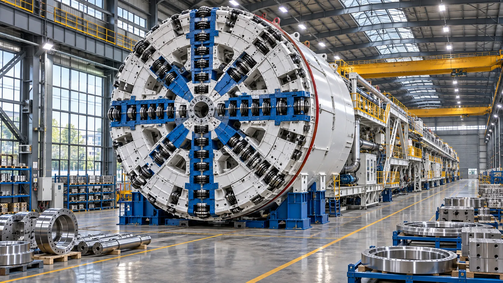
China Sets Tunnel Boring Machine Export Controls as India Pushes Local Production
China tunnel boring machine export controls could reshape procurement as India pushes local production. Explore potential supply and project impacts.
Choosing a Trenchless Pipeline Installation Contractor: Key Qualifications
Choose a trenchless pipeline installation contractor with confidence. Learn how to assess experience, equipment, safety, costs, and project risks before you hire.
Related News
- 00
0000-00
China's TBM Export Controls Prompt Infrastructure Concerns in India - 00
0000-00
How TBM Excavation Works in Rock and Soft Ground: A Practical Guide - 00
0000-00
Choosing a Zero-Emission Underground Equipment Supplier: What to Check - 00
0000-00
Construction Starts on Germany's Pfaffensteig Rail Tunnel, With Two TBMs Planned - 00
0000-00
How Real-Time Underground Mapping Systems Work in Tunneling
Weekly Insights
Stay ahead with our curated technology reports delivered every Monday.