
How Real-Time Underground Mapping Systems Work in Tunneling





How can tunneling teams navigate accurately when GPS signals cannot penetrate the ground? Underground mapping systems combine real-time sensor data, positioning algorithms, and 3D models.
For technical evaluators, the key question is whether those components deliver information accurate, timely, and reliable enough for a specific engineering decision.
A live visualization is not proof of survey accuracy or a guarantee that hazards ahead have been detected. Performance depends on measurement methods, ground conditions, integration, and independent verification.
What Does a Real-Time Underground Mapping System Actually Do?
A real-time underground mapping system connects measurements from underground instruments to a spatial model that updates as excavation or surveying progresses.
Depending on its configuration, it can show the tunnel boring machine’s position and orientation, the excavated tunnel geometry, installed segments, and selected geological observations.
These functions are related but distinct. Machine guidance estimates where the TBM is; mapping records surrounding geometry or conditions; geological prediction assesses material beyond the excavation face.
One platform may combine all three, but a conventional laser scanner cannot see through intact rock, and a position estimate does not independently validate geological predictions.
For procurement, define the decision first: steering a machine, checking clearance, documenting construction, or investigating ground ahead. Each requires different sensors and evidence.
How Is the TBM Located Without GPS?
Most projects establish a surveyed control network from known surface reference points and transfer that control underground through a portal, shaft, or other suitable access.
Survey teams extend the network as the tunnel advances. Total stations, prisms, and laser guidance equipment can then relate machine measurements to the project coordinate system.
A guidance system typically estimates the TBM’s position and orientation using reference measurements and onboard instruments such as inclinometers, gyroscopes, and displacement sensors.
The resulting pose is compared with the design alignment. Operators receive deviations and steering information that support adjustments to the machine’s articulation or thrust.
Long drives complicate this process: restricted sightlines, refraction, vibration, and accumulated survey uncertainty can all affect positioning. Control networks therefore require periodic checking and adjustment.
Inertial systems can bridge short interruptions in external references, but their estimates drift over time. They need reliable updates or checks against established survey control.
SLAM, or simultaneous localization and mapping, can estimate movement from observed features while building a map. Its performance depends on environment, sensor configuration, and loop closure opportunities.
Repetitive tunnel linings, dust, water spray, and moving machinery can make features difficult to distinguish. SLAM should not automatically be treated as a replacement for controlled engineering survey.
Which Sensors Build the Underground Model?
Laser scanners and lidar measure distances to visible surfaces, producing point clouds that describe tunnel profiles, lining geometry, equipment, and other exposed features.
Cameras provide visual context and can support photogrammetry or visual SLAM when lighting, visibility, and surface texture are sufficient for reliable image matching.
Total stations and prisms provide controlled geometric observations. Inertial measurement units supply motion and orientation data, while encoders can contribute machine or vehicle movement estimates.
On a TBM, operational measurements such as thrust, torque, penetration rate, and cutterhead speed add excavation context. They are indirect indicators, not direct geological identification.
For investigations ahead of the face, a project may use seismic probing, ground-penetrating radar, probe drilling, or other methods suited to its geology and machine configuration.
Each method has limits. Radar penetration depends on material properties, seismic interpretations depend on acquisition and processing, and probe holes sample only their drilled paths.
Assess a vendor’s sensor package against the intended output: surface geometry, machine pose, ground characterization, or a combination. Ask which measurements directly support each displayed result.
How Does Sensor Data Become a Usable Map?
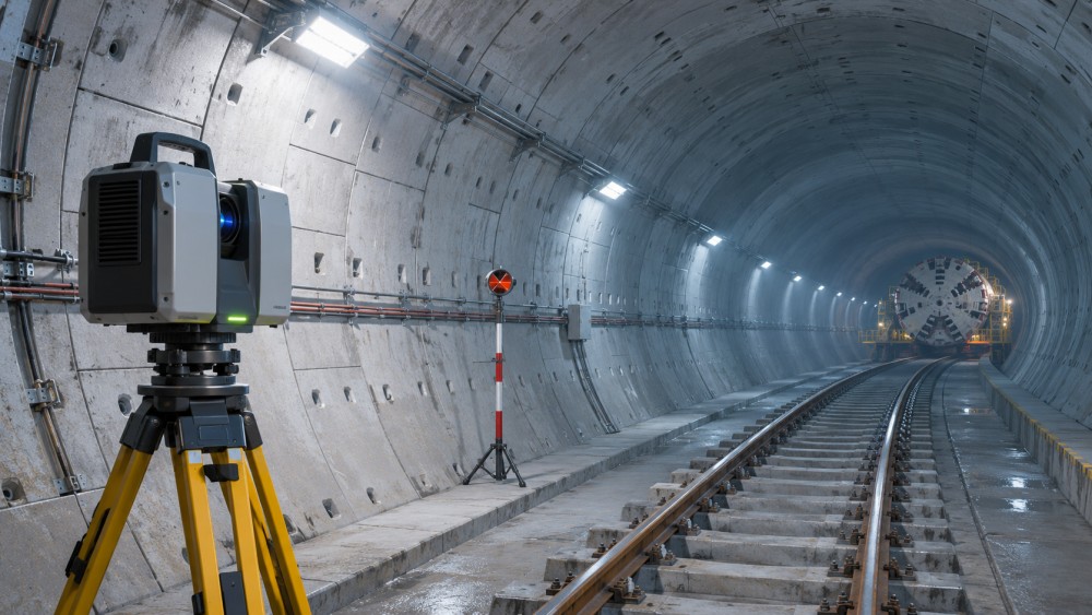
The processing chain begins with sensor acquisition. Each observation needs a timestamp and an understood relationship to the sensor’s mounting position and orientation.
Calibration establishes those relationships between instruments, the machine, and the project reference frame. An error in a mounting offset can shift otherwise precise measurements.
Software then filters observations, estimates position and orientation, and registers measurements into a common coordinate system. The resulting model may combine point clouds, alignment data, and machine telemetry.
Sensor fusion can improve continuity by combining complementary measurements, but it cannot remove every systematic error. Shared reference or calibration errors may affect multiple outputs together.
The system compares current observations with design geometry or previous surveys. Depending on the application, it may flag alignment deviation, clearance conflicts, or incomplete coverage.
Finally, the model is displayed locally or transmitted to a project platform. The interface should show observation age and quality, not just a current-looking visualization.
For each output, evaluators should trace the chain from raw measurement to displayed result, including coordinate transformations, processing assumptions, and any manual interpretation.
What Does “Real Time” Mean in Practice?
Real time does not imply zero delay. A useful definition states how quickly data must reach a decision-maker and how old it may be when acted upon.
Steering feedback may need a faster and more predictable update cycle than a construction progress dashboard. The required latency should follow the operational decision.
Measure latency across the complete chain: acquisition, processing, network transmission, display, and any alert delivery. An instrument’s sampling rate alone is not the answer.
Underground connectivity can be interrupted by distance, equipment movement, or infrastructure failures. Local buffering and edge processing can preserve selected functions when links are unavailable.
Ask which functions remain operational offline, how long data can be stored, and how the system reconciles buffered records after communication is restored.
Alerts should distinguish stale data, lost tracking, and degraded measurement quality from genuine changes in alignment or ground conditions. Otherwise, operators may misinterpret the display.
How Accurate Is the Mapping, and How Can It Be Verified?
There is no single accuracy figure for an entire system. Position, orientation, surface geometry, and predicted ground conditions have different error sources and validation methods.
Specify tolerances in the project coordinate system and at the location where decisions are made. Also define confidence, operating conditions, and the time period over which performance applies.
Machine pose uncertainty can propagate into a scan: even a precise range measurement may be misplaced if the sensor position or orientation is wrong.
Accuracy also varies with distance, surface reflectivity, visibility, geometry, calibration, and survey control. Vendor specifications measured under favorable conditions may not represent the tunnel.
Validate position and alignment against independent survey observations, using agreed checkpoints along the drive. Avoid relying solely on measurements used to establish the system’s own control.
For geometry, compare registered point clouds or derived profiles with independently surveyed reference points. Report residuals, coverage gaps, and conditions during acquisition.
For ground prediction, compare documented forecasts with subsequent excavation records, probe results, or mapped exposures. Record both missed features and false indications.
A practical acceptance plan defines test locations, required tolerances, repeatability, reporting format, and corrective actions when results fall outside the agreed limits.
Where Does Mapping Create Operational Value?
TBM guidance can help crews monitor alignment continuously and identify deviations earlier, supporting timely steering decisions and reducing reliance on intermittent checks alone.
Scanning completed tunnel sections can support clearance assessment, lining documentation, and comparison with design. Its value depends on sufficient coverage and verified registration.
Linked machine telemetry and geological observations can help engineers investigate changes in excavation behavior. Correlation should prompt examination, not substitute for geotechnical judgment.
In drill-and-blast tunnels, mapping exposed faces and excavation profiles can support geological logging, overbreak assessment, and planning for subsequent rounds.
For pipe jacking, accurate position and alignment information can support guidance through constrained urban corridors, subject to the available reference method and project tolerances.
These applications can reduce rework or improve decision speed, but benefits should be demonstrated against a baseline. Equipment cost alone does not establish return on investment.
What Can Cause a System to Underperform?
Dust, water, poor lighting, and reflective surfaces can degrade optical sensing. Shielding, cleaning, mounting locations, and suitable sensing redundancy deserve attention during design.
Vibration and machine movement can affect measurements or calibration. Maintenance procedures should specify inspection intervals and checks after impacts, component replacement, or sensor relocation.
Coordinate mistakes are another serious risk. Datum, units, axis conventions, and transformation parameters must remain consistent across survey, guidance, design, and reporting systems.
Data integration can fail even when sensors work well. Proprietary formats, incomplete timestamps, and undocumented interfaces may prevent teams from reproducing or independently checking results.
Human factors matter too. Operators need clear ownership of alerts, escalation thresholds, and authority to stop or investigate when measurements disagree with site observations.
Mapping and prediction tools support engineering decisions; they do not replace the project’s ground investigation, survey controls, safe working procedures, or emergency response arrangements.
How Should Technical Evaluators Compare Systems?
Start with representative use cases and measurable acceptance criteria. Separate mandatory safety and survey requirements from convenience features such as remote dashboards or automated reporting.
Request evidence from comparable ground conditions, tunnel dimensions, machine configurations, and drive lengths. A demonstration in an accessible test space may not reveal underground limitations.
Use the following questions to structure a technical evaluation and make vendor claims comparable:
- Which outputs are measured directly, and which are inferred? What assumptions and confidence information accompany each result?
- How are control points established, transferred, checked, and updated? How does positioning uncertainty change as the drive advances?
- What are the end-to-end latency, update rate, coverage, and tested accuracy for each intended operating mode?
- What happens during sensor obstruction, tracking loss, power interruption, or network failure? How are users warned?
- Which raw data, calibration records, timestamps, and coordinate transformations can the project export and audit?
- How are alerts configured, validated, acknowledged, and escalated? Can thresholds be adapted to project procedures?
- What installation time, survey support, maintenance, training, licensing, and cybersecurity controls are required over the project lifecycle?
A site trial should include normal production, planned outages, and representative visibility challenges. Compare results with independent survey and documented operational observations.
Agree on data ownership, retention, interface responsibilities, and support response times before deployment. These provisions affect long-term usability as much as the initial demonstration.
Making a Confident Selection
Real-time underground mapping is most useful when its measurements, update speed, and uncertainty match a defined tunneling decision and are verified under representative conditions.
Choose systems that make limitations visible, preserve traceable data, and integrate with survey and operational workflows. Treat underground visualization as evidence to assess, not certainty.
Related News
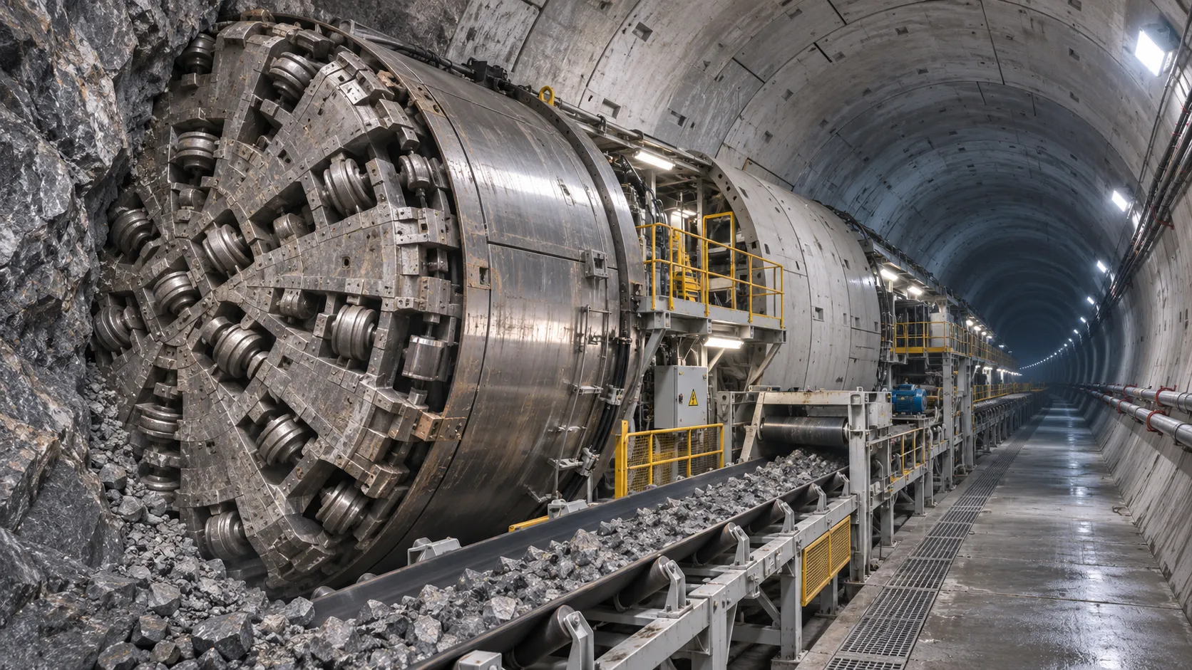
How TBM Excavation Works in Rock and Soft Ground: A Practical Guide
TBM Excavation in rock and soft ground explained: compare machine types, ground support, spoil removal, and the factors that guide smarter project planning.
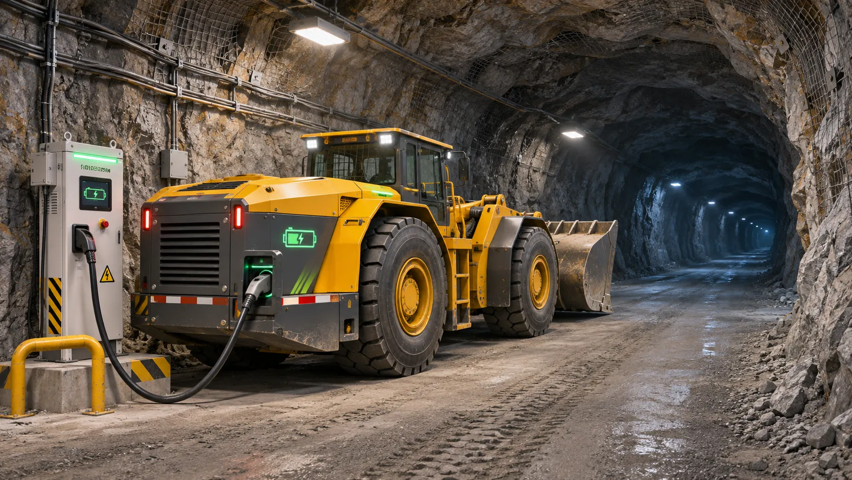
Choosing a Zero-Emission Underground Equipment Supplier: What to Check
Choosing a zero emission underground equipment supplier? Compare duty-cycle performance, charging, safety, total costs and support before you commit.
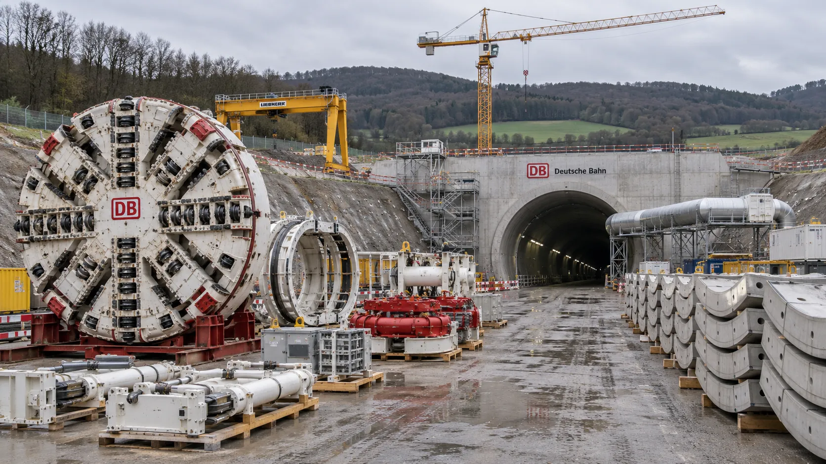
Construction Starts on Germany's Pfaffensteig Rail Tunnel, With Two TBMs Planned
Pfaffensteig rail tunnel construction is underway in Germany. Discover how two planned TBMs will support the 11-kilometre project near Stuttgart.
First Mechanized Tunnel Crossing Beneath the Panama Canal Completed
Panama Canal tunnel crossing: Explore the reported Metro Line 3 milestone and what it could mean for future underwater tunneling projects.
Underground Utility Construction Equipment: Choosing by Ground Conditions
Choose underground utility construction equipment with confidence. Compare trenching, HDD, microtunnelling and TBMs by ground conditions, risk and cost.
China Sets Tunnel Boring Machine Export Controls as India Pushes Local Production
China tunnel boring machine export controls could reshape procurement as India pushes local production. Explore potential supply and project impacts.
Choosing a Trenchless Pipeline Installation Contractor: Key Qualifications
Choose a trenchless pipeline installation contractor with confidence. Learn how to assess experience, equipment, safety, costs, and project risks before you hire.
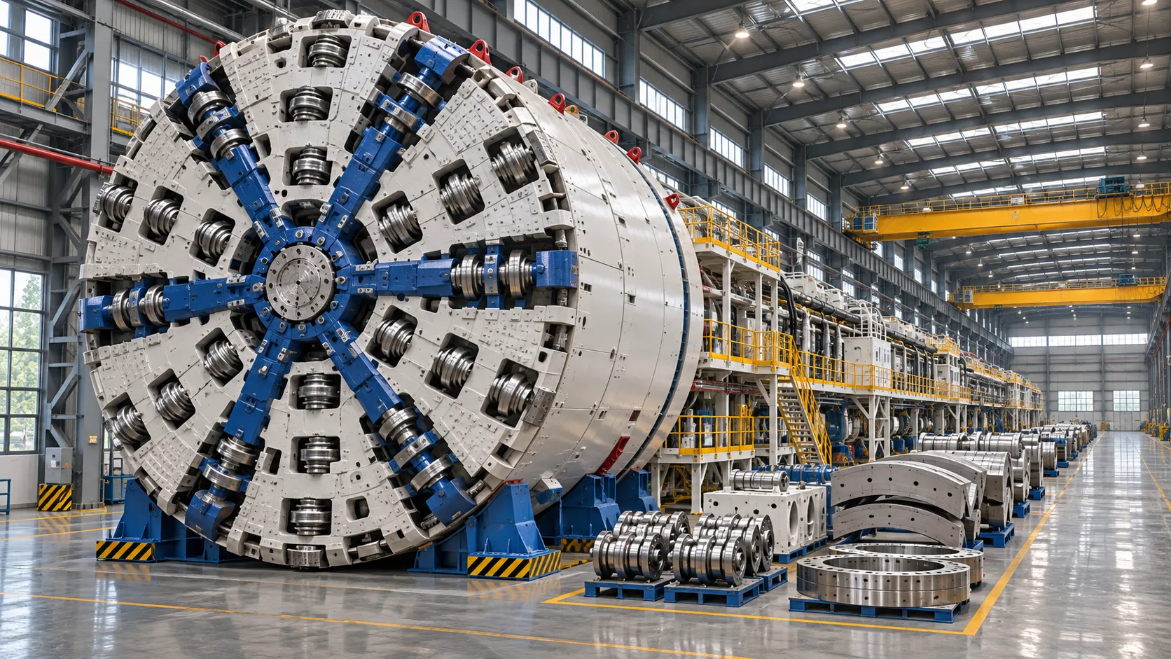
China's 70% TBM Share and Export Controls Challenge India's Local Production
China's TBM export controls could challenge India's local production and infrastructure sourcing. Explore the potential risks and procurement options.
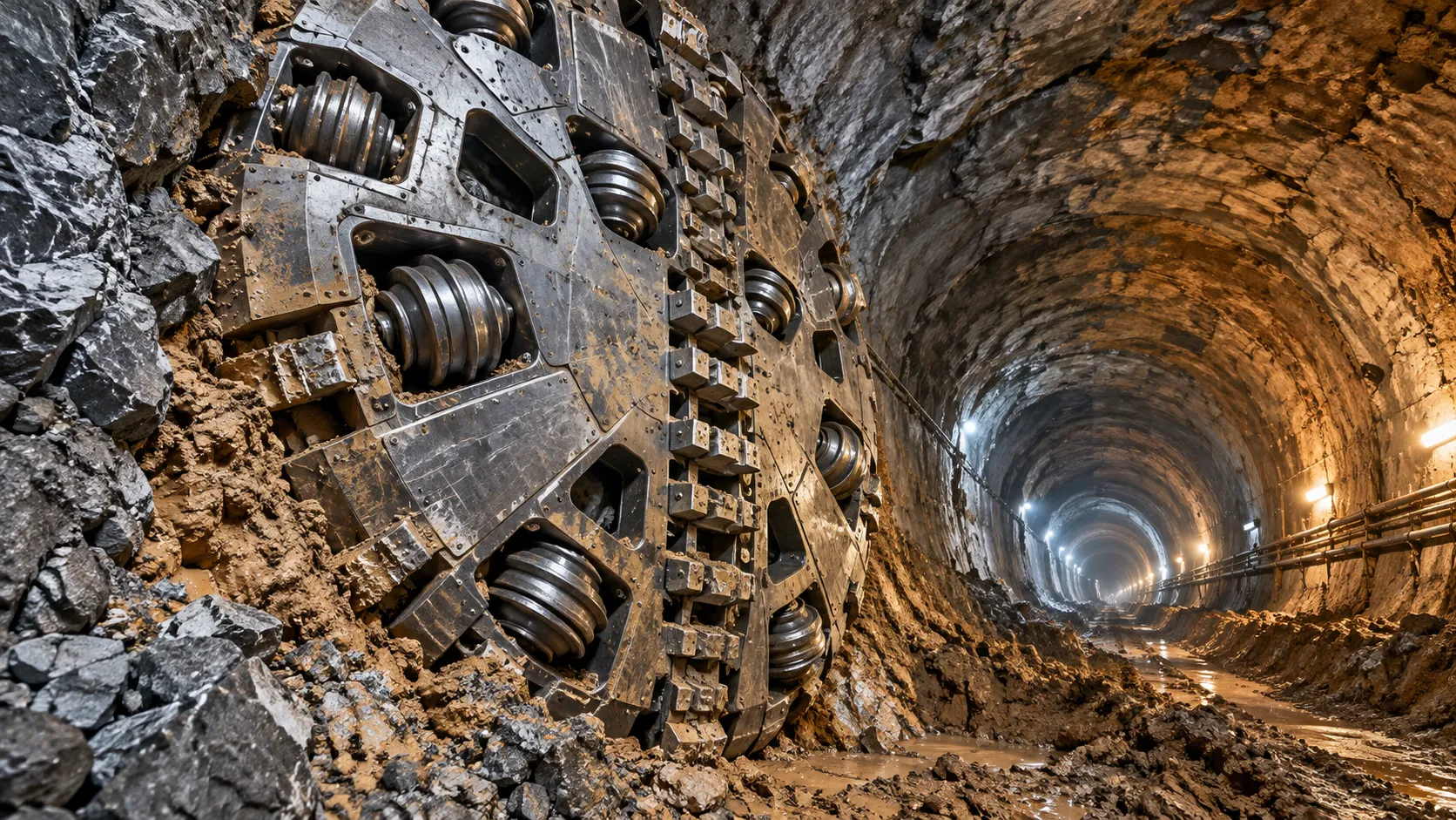
TBM Cutterheads for Mixed Ground: Selecting Cutters for Rock and Soil
Explore TBM cutterheads for mixed ground and learn how to select cutters, manage rock–soil transitions, and reduce wear, downtime, and intervention risk.
Related News
- 00
0000-00
How TBM Excavation Works in Rock and Soft Ground: A Practical Guide - 00
0000-00
Choosing a Zero-Emission Underground Equipment Supplier: What to Check - 00
0000-00
Construction Starts on Germany's Pfaffensteig Rail Tunnel, With Two TBMs Planned - 00
0000-00
How Real-Time Underground Mapping Systems Work in Tunneling - 00
0000-00
First Mechanized Tunnel Crossing Beneath the Panama Canal Completed
Weekly Insights
Stay ahead with our curated technology reports delivered every Monday.