
Friction Rock Bolts: How Borehole Diameter Affects Pull-Out Resistance





When friction rock bolts install unusually easily or produce inconsistent pull-test results, borehole diameter is one of the first variables to investigate. For split-tube bolts, an oversized hole generally reduces radial interference, contact pressure, and pull-out resistance. A smaller hole can increase anchorage, but only within the bolt’s approved installation range: excessive interference can cause installation refusal, tube damage, or incomplete embedment.
The acceptable drilling tolerance therefore cannot be selected from bolt diameter alone. It must connect the specific bolt design, actual hole geometry, ground conditions, and representative pull testing. Hydraulically expanded bolts require a different assessment because their anchorage develops through expansion against the borehole wall, rather than insertion of an oversized split tube. Treating these systems as interchangeable can produce misleading specifications and unsafe acceptance decisions.
The mechanical link between hole size and anchorage
A split-tube friction bolt has an uninstalled outside diameter larger than its intended borehole. Driving it into the hole compresses the tube and narrows its longitudinal slot. Elastic recovery generates outward pressure against the rock, allowing axial load to transfer through friction along the installed length.
A simplified expression for the frictional contribution to axial resistance is:
F ≈ ∫ μ(x) p(x) C(x) dx
Here, μ is the local interface friction coefficient, p is contact pressure, C is the effective contact perimeter, and integration extends over the engaged length. Assuming uniform conditions reduces this to F ≈ μpCL. This is a conceptual relationship, not a stand-alone design equation: contact is rarely uniform, and tube deformation, borehole roughness, local bearing, and rock damage complicate the response.
Increasing borehole diameter slightly increases the available circumference, but that does not compensate for lost interference. For a split-tube system, the reduction in contact pressure usually dominates. An oversized interval may contribute little anchorage even when the bolt appears fully installed.
Reducing diameter increases tube compression, but the response is not indefinitely beneficial. Once the slot approaches closure, deformation mechanisms change and insertion resistance can rise sharply. Driving harder may then damage the bolt, crush weak borehole walls, or leave insufficient embedment. The practical target is a qualified installation window, not the smallest drillable hole.

Separate split-tube and hydraulically expanded systems
An expanded bolt may accommodate a wider range of hole sizes than a particular split-tube product, but this must be verified for the actual design. An excessively large hole may exceed its expansion capability or produce inadequate wall engagement. A very small or irregular hole can interfere with insertion and expansion. Successful pressurization alone does not establish the required pull-out resistance.
For expanded systems, pressure, hold time, leakage, equipment calibration, and the manufacturer’s installation procedure belong in the evaluation alongside diameter. Hydraulic expansion pressure must not be treated as identical to residual rock-contact pressure after installation.
Neither system should inherit another product’s borehole tolerance because its nominal diameter or steel strength looks similar. Tube geometry, wall thickness, material properties, surface condition, and installation equipment can change the diameter–resistance relationship.
Measure the hole the bolt actually encounters
A drill bit’s marked diameter is a tooling specification, not proof of the finished hole diameter. Bit wear can reduce gauge, while drill-string movement, collar instability, joint intersections, and wall breakout can enlarge selected intervals. A hole may simultaneously contain tight sections, oval sections, and cavities.
This matters because a bolt reacts to local geometry. One tight interval can produce high driving resistance while most of the remaining length sits in an oversized hole. Conversely, a sound collar can conceal enlargement deeper in the excavation-damaged zone. Installation effort alone cannot distinguish these conditions.
- Record bit condition: check gauge and wear using a consistent method, and link each test hole to the bit and drilling setup used.
- Inspect geometry along depth: where access and equipment permit, use a suitable borehole gauge, caliper, or inspection method rather than relying only on the collar.
- Capture irregularity: record minimum and maximum dimensions where measurable, not merely an average that hides ovality or breakout.
- Log wall condition: identify weak bands, open joints, cavities, and disturbed collars that may reduce effective contact length.
Measurement limitations should remain visible in the test record. A gauge that cannot pass a constriction does not establish the diameter beyond it. Measurements in accessible trial holes may also be unrepresentative of overhead production holes unless drilling orientation, ground, and operating conditions are comparable.
Diagnosing low resistance without blaming diameter too early
The same low pull load can arise from different mechanisms. Diameter should be investigated alongside embedment, bolt condition, and rock response, rather than used as the default explanation.
Weak rock creates a particularly important exception to simple interference reasoning. A tighter hole may initially demand more driving force, yet wall crushing or relaxation can reduce sustained contact pressure. Roughness can improve engagement, but highly fractured walls may lose confinement under load. Neither roughness nor high insertion effort is a reliable substitute for verified anchorage.
Water, drilling residue, corrosion, and time-dependent ground movement can also alter interface behavior. Their significance depends on the site and service period. Immediate tests in freshly drilled holes should not automatically be interpreted as evidence of long-term performance under different conditions.
Build a pull-test program that isolates diameter effects
A useful qualification program compares controlled diameter groups within representative ground. Simply pooling production tests from different rock types and bolt lengths can hide the relationship being investigated.
- Define the required response. Establish the design basis, test objective, target loads, acceptable displacement, and relevant failure criteria before testing. Distinguish qualification tests from routine proof tests.
- Select diameter groups within approved limits. Investigate the intended operating range and its boundaries without deliberately installing outside manufacturer restrictions unless a separately engineered trial procedure permits it.
- Control other variables. Keep bolt design, installed length, installation procedure, and test setup comparable. Record unavoidable differences rather than assuming they cancel out.
- Represent production variability. Include relevant rock domains, bit-wear states, orientations, and drilling conditions. Use enough replicates to assess scatter; one successful test cannot establish a tolerance.
- Measure load and displacement. Record the loading sequence and movement, not only the highest displayed load. Note slip onset, progressive movement, and the observed failure mode.
- Review the lower-performing results. Examine repeatability and the applicable statistical acceptance approach instead of qualifying a diameter from its average resistance alone.
The pull rig must be calibrated, aligned with the bolt, and compatible with its head or test adaptor. Its reaction arrangement should follow the chosen method and avoid unintended confinement that masks the mechanism under investigation. Displacement measurement should distinguish bolt movement from fixture seating and apparatus compliance as far as practicable.
A proof test that stops at a prescribed load shows whether the tested assembly sustained that loading under the stated acceptance criteria. It does not measure ultimate pull-out capacity. Similarly, a test ending in steel rupture establishes a different limit from interface sliding; the results should not be grouped as equivalent pull-out failures.
Where adopted by the project, ASTM D4435 provides a rock-bolt anchor pull-test framework. Confirm the applicable edition, scope, and suitability for the friction-bolt assembly and test purpose. A test standard does not itself supply a universal borehole tolerance or convert a measured peak load into an allowable support capacity.
Turn the evidence into a drilling tolerance
A defensible specification states an allowable finished-hole range for a named bolt design in defined ground and installation conditions. It also identifies how that range will be controlled in production. A nominal bit size without wear limits, inspection requirements, or verification testing leaves the main uncertainty unresolved.
The lower diameter boundary should reflect installability, full embedment, and freedom from unacceptable bolt or wall damage. The upper boundary should reflect the required anchorage response, including displacement and variability. Both boundaries must remain consistent with the manufacturer’s limits and the project’s ground-support design.
Qualification near a boundary deserves particular scrutiny. A diameter that passes only in competent rock, with fresh tooling and carefully aligned installation, may not be a robust production limit in fractured ground. Set operating targets far enough inside the qualified window to accommodate demonstrated drilling variation; do not invent a generic margin disconnected from measurements.
Production acceptance should connect three records: drilling condition, bolt installation, and verification testing. Define actions for out-of-range holes, incomplete installation, abnormal driving behavior, and failed proof tests. These may include additional investigation, replacement holes, or an approved alternative support detail—not simply installing the same bolt and assuming surrounding bolts compensate.
When the diameter–resistance relationship must be requalified
Reassessment is warranted when the bolt design changes, drilling equipment or tooling materially changes hole geometry, or excavation enters ground outside the qualified domain. Persistent shifts in installation behavior or pull-test scatter also justify investigation, even when the nominal bit size remains unchanged.
Pull-out resistance remains only one part of support adequacy. A bolt can meet an axial test requirement yet be unsuitable for the expected deformation, joint shear, corrosion exposure, or dynamic loading. Those checks belong to the ground-support design. For diameter control specifically, the decision is narrower: demonstrate that the actual hole range permits reliable installation and achieves the specified anchorage response, then verify that production drilling stays within that qualified range.
Related News
China's TBM Export Controls Prompt Infrastructure Concerns in India
China's TBM export controls could affect infrastructure projects in India. Explore potential supply risks and practical procurement steps.
How TBM Excavation Works in Rock and Soft Ground: A Practical Guide
TBM Excavation in rock and soft ground explained: compare machine types, ground support, spoil removal, and the factors that guide smarter project planning.
Choosing a Zero-Emission Underground Equipment Supplier: What to Check
Choosing a zero emission underground equipment supplier? Compare duty-cycle performance, charging, safety, total costs and support before you commit.
Construction Starts on Germany's Pfaffensteig Rail Tunnel, With Two TBMs Planned
Pfaffensteig rail tunnel construction is underway in Germany. Discover how two planned TBMs will support the 11-kilometre project near Stuttgart.
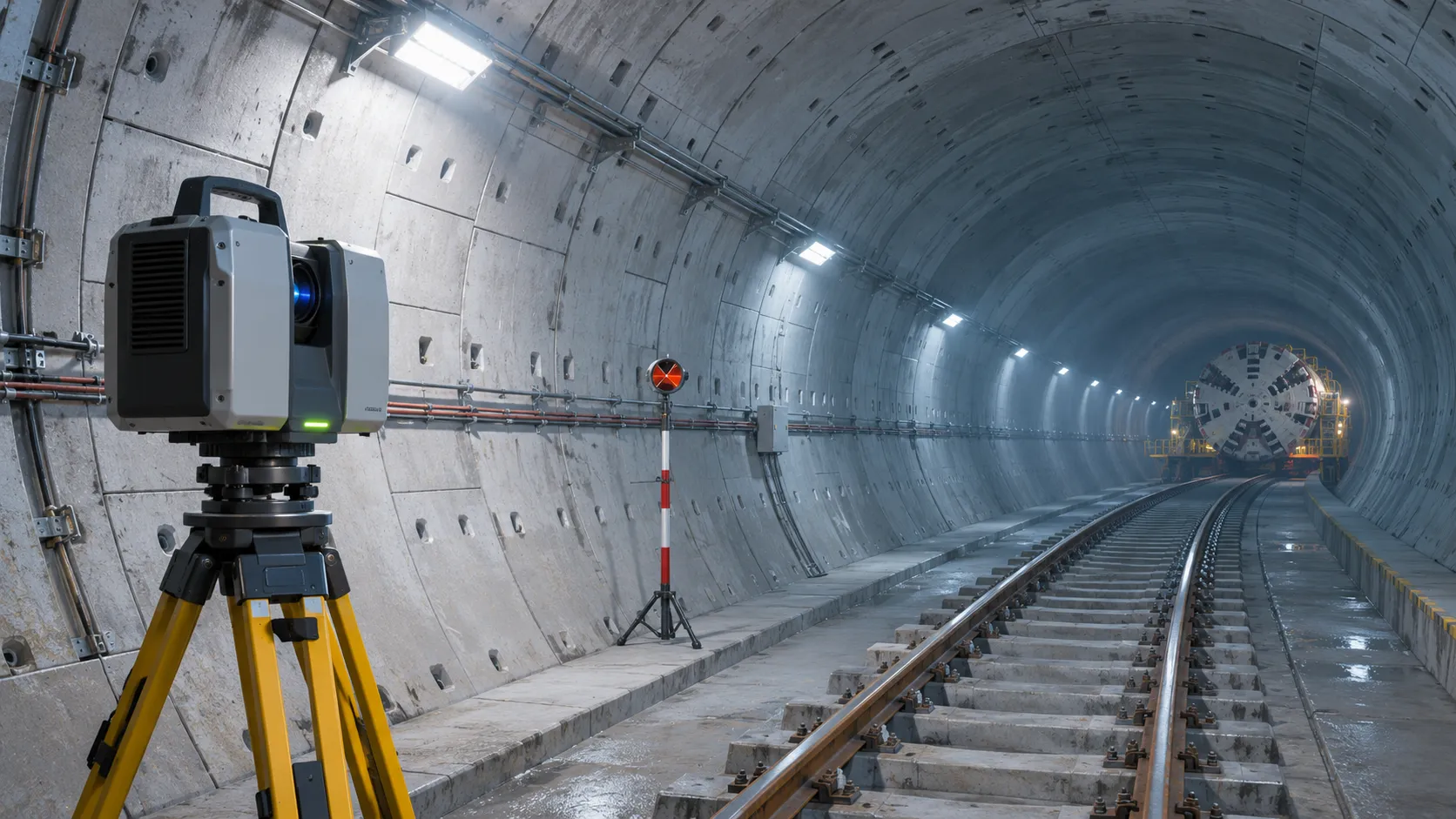
How Real-Time Underground Mapping Systems Work in Tunneling
Discover how real-time underground mapping systems guide tunneling teams, integrate sensor data, and support confident decisions with verified accuracy.
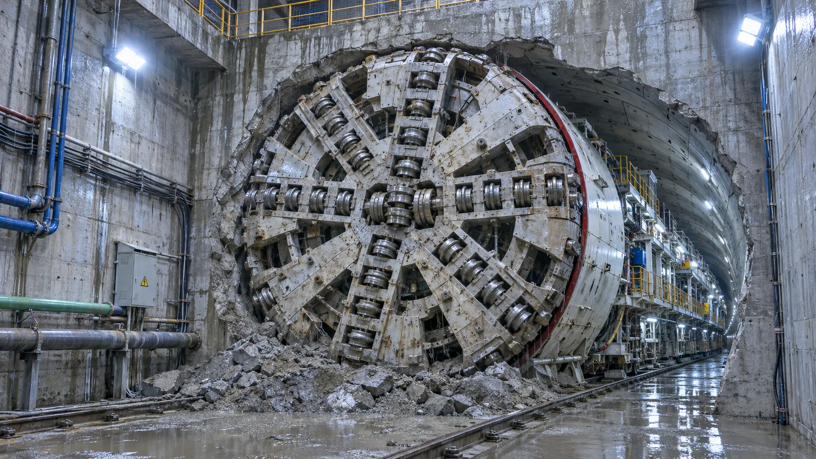
First Mechanized Tunnel Crossing Beneath the Panama Canal Completed
Panama Canal tunnel crossing: Explore the reported Metro Line 3 milestone and what it could mean for future underwater tunneling projects.
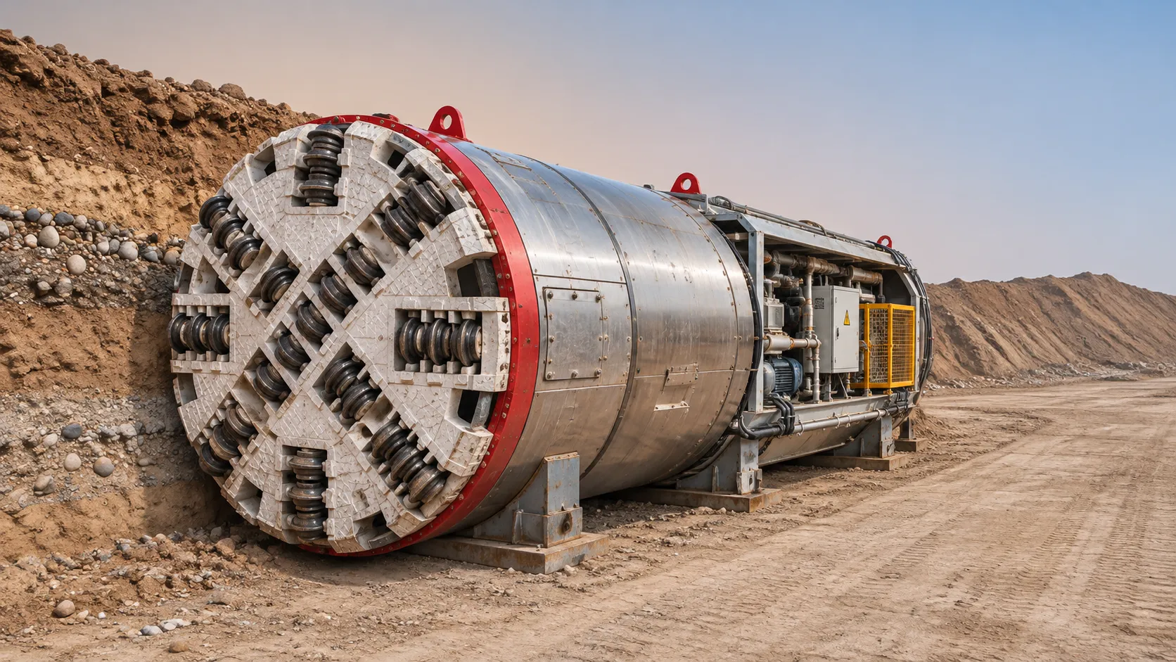
Underground Utility Construction Equipment: Choosing by Ground Conditions
Choose underground utility construction equipment with confidence. Compare trenching, HDD, microtunnelling and TBMs by ground conditions, risk and cost.
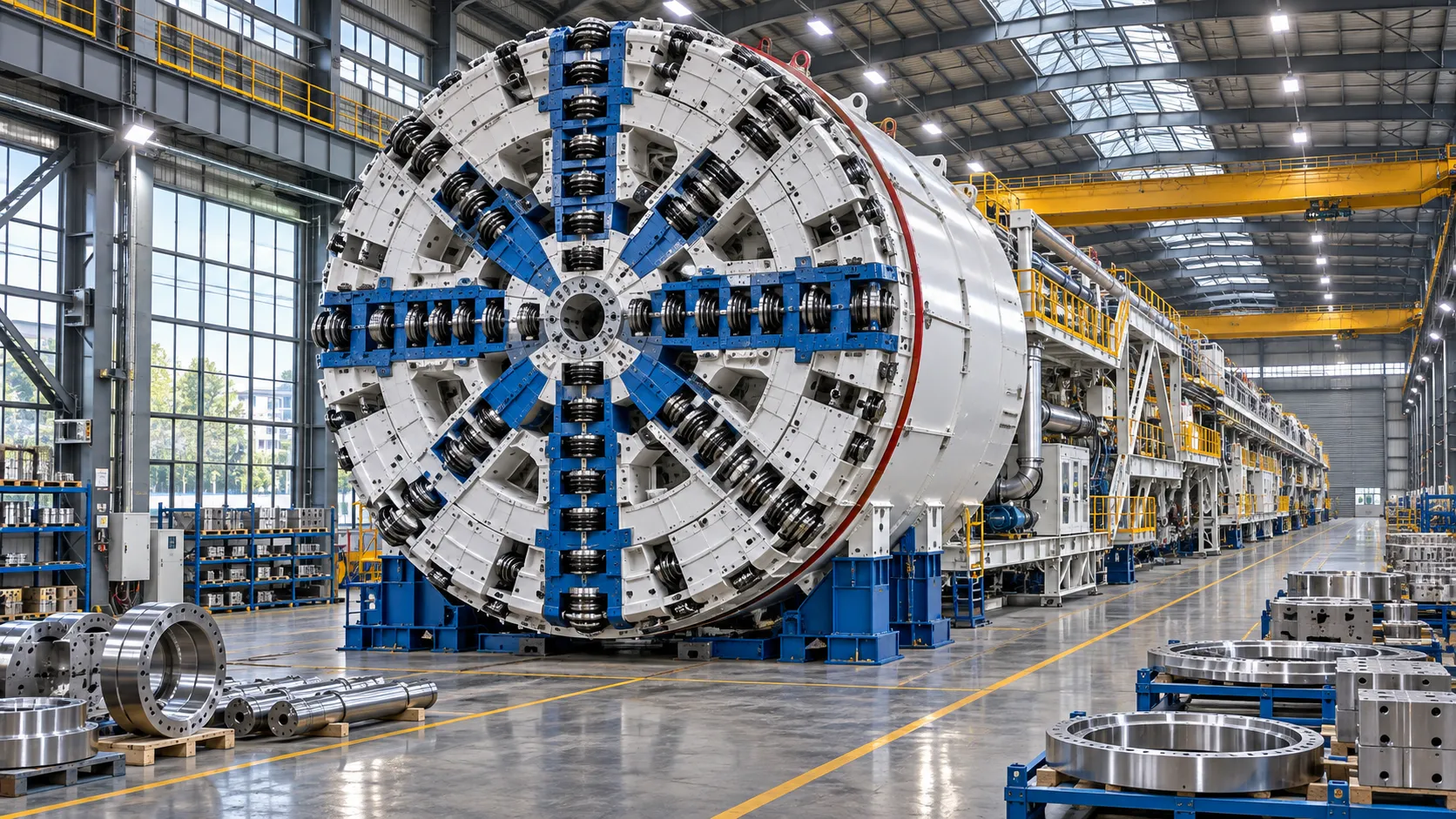
China Sets Tunnel Boring Machine Export Controls as India Pushes Local Production
China tunnel boring machine export controls could reshape procurement as India pushes local production. Explore potential supply and project impacts.
Choosing a Trenchless Pipeline Installation Contractor: Key Qualifications
Choose a trenchless pipeline installation contractor with confidence. Learn how to assess experience, equipment, safety, costs, and project risks before you hire.
Related News
- 00
0000-00
China's TBM Export Controls Prompt Infrastructure Concerns in India - 00
0000-00
How TBM Excavation Works in Rock and Soft Ground: A Practical Guide - 00
0000-00
Choosing a Zero-Emission Underground Equipment Supplier: What to Check - 00
0000-00
Construction Starts on Germany's Pfaffensteig Rail Tunnel, With Two TBMs Planned - 00
0000-00
How Real-Time Underground Mapping Systems Work in Tunneling
Weekly Insights
Stay ahead with our curated technology reports delivered every Monday.