
TBM Cutterheads for Mixed Ground: Selecting Cutters for Rock and Soil





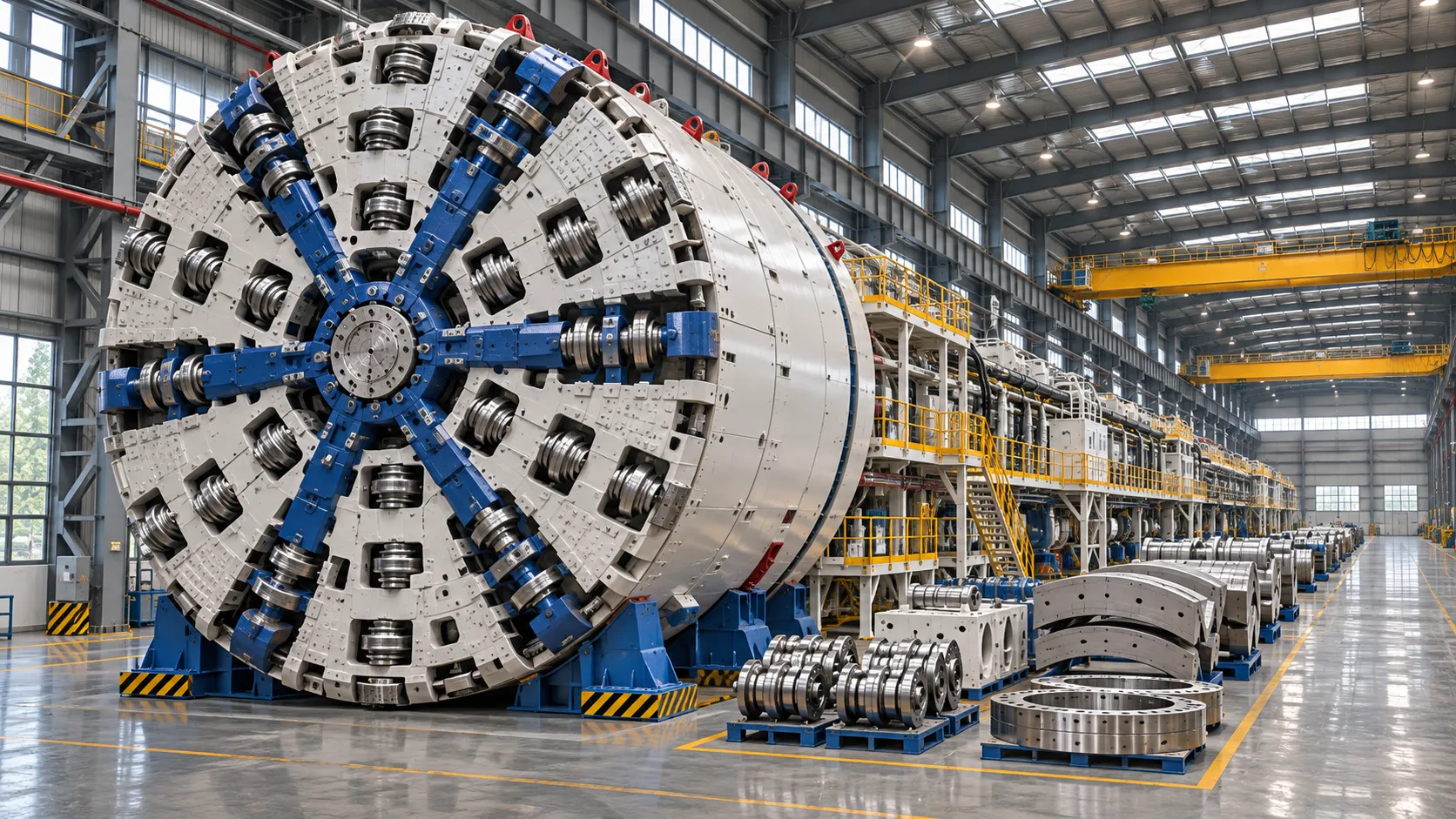
Selecting TBM cutterheads for mixed ground requires more than balancing rock-cutting capacity against soil excavation. Abrupt changes in strength, abrasivity, groundwater conditions, and face stability can alter cutter wear, penetration rates, and intervention risk across a single drive.
For technical evaluators, the choice and arrangement of disc cutters and soft-ground tools must be assessed alongside cutterhead openings, soil conditioning, and maintenance access.
The strongest specification is not necessarily the one with the largest cutters or greatest opening ratio. It is the one that manages the most consequential ground transitions while retaining controllable excavation, reliable muck removal, and feasible tool replacement.
Which Ground Conditions Should Drive Cutterhead Selection?
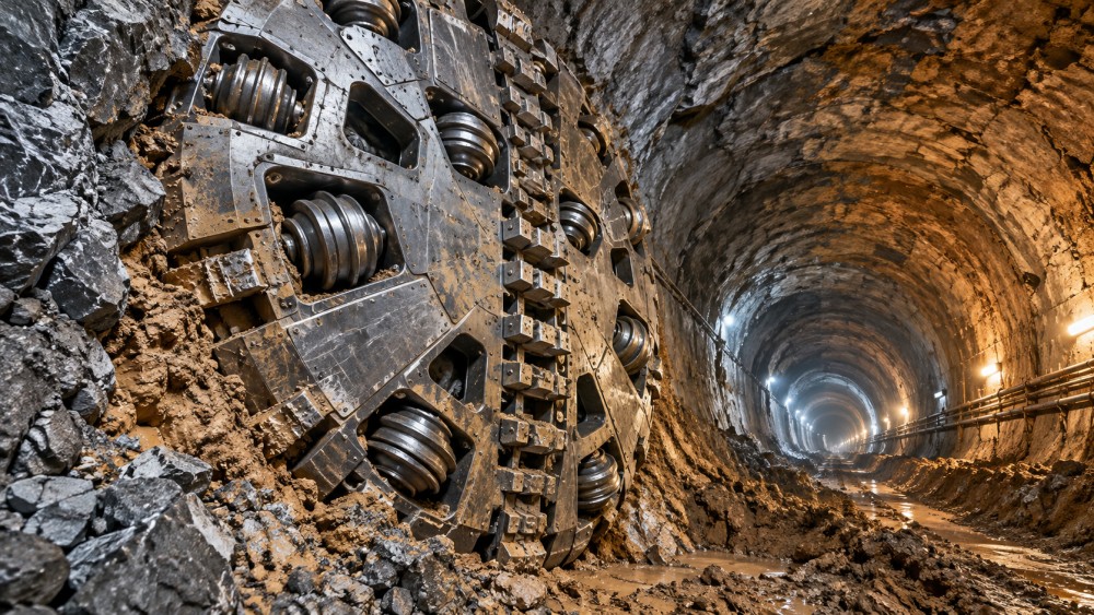
Start with the ground expected across the tunnel face, not just the geological units along the alignment. A face containing rock and soil simultaneously imposes different demands from a drive passing through separate, relatively uniform zones.
Map the anticipated proportions of rock and soil, the orientation of their boundary, and the distance over which the interface may move across the face. Include uncertainty between investigation points.
Strong rock below weak soil can cause uneven cutting resistance, vibration, and steering difficulty. A steep or irregular interface may also load different cutterhead sectors unevenly as excavation progresses.
Assess intact rock strength alongside rock mass conditions. Joint spacing, joint orientation, block size, weathering, and discontinuity infill influence breakage and block formation; unconfined compressive strength alone cannot predict performance.
For soil, examine grain size distribution, plasticity, cohesion, density, permeability, and clogging tendency. Cobbles and boulders deserve separate attention because their size and strength affect both cutting and chamber discharge.
Groundwater pressure, inflow potential, and the consequences of losing face support are equally important. These conditions influence machine type, intervention method, sealing requirements, and the acceptable cutterhead opening arrangement.
Use a geological baseline and a range of credible scenarios to evaluate the design. A single average strength or abrasivity value can conceal the short sections that dominate wear, delay, or intervention exposure.
Disc Cutters, Scrapers, or Both?
Disc cutters are generally selected where rock must be fractured efficiently. Their rings concentrate load on the face, creating cracks and chips when sufficient thrust is available under the actual contact conditions.
Scrapers, drag bits, and cutting knives are commonly used for soil and weaker formations. Their geometry promotes excavation and flow, but abrasive ground can consume exposed material quickly and increase replacement frequency.
A mixed-ground cutterhead often combines both tool types. Disc cutters address competent rock, while scrapers or cutting bits work soil and weaker material; the precise combination depends on geology and machine design.
Hybrid arrangements involve compromises. A tool optimized for rock may contribute little in soft soil, while protruding soil tools may suffer impact damage or excessive wear when repeatedly encountering hard rock.
Check the relative projection of discs and scrapers throughout their wear life. The initial geometry should not become ineffective when one tool type wears faster, changes the cutting profile, or shields another tool.
Replaceable wear protection, hardfacing, and abrasion-resistant materials can extend component life. Their selection should consider impact resistance as well as abrasion, because a hard surface is not automatically the most durable choice.
For boulder-bearing soil, evaluate the expected block size against the cutting tools, chamber geometry, and discharge system. A cutterhead capable of breaking rock does not guarantee that every resulting block can be removed.
How Should Disc Size, Spacing, and Layout Be Evaluated?
Disc diameter, ring profile, bearing capacity, and mounting arrangement should be assessed together. Larger discs may offer advantages in some hard-rock applications, but they also affect space, loading, replacement logistics, and machine weight.
Check whether the machine can deliver adequate cutter load at the anticipated face contact area. Installed total thrust alone is insufficient: mixed ground may leave some discs lightly loaded while others carry disproportionate forces.
Disc spacing influences how cracks from adjacent cutting paths interact. An effective layout depends on penetration, rock properties, and cutter geometry; a spacing suitable for one formation may perform poorly in another.
Review coverage from the center to the gauge. The central zone has limited peripheral speed and congested tool arrangements, while gauge cutters experience demanding wear and are critical to maintaining excavation diameter.
At rock–soil interfaces, examine whether the arrangement remains effective as the boundary moves. Sector loading, vibration, and uneven wear can change with each rotation, particularly when strong rock occupies only part of the face.
Ask the manufacturer for predicted cutter forces, penetration, torque, and wear under several face compositions. Confirm the assumptions behind each model and identify conditions outside the available reference experience.
Can Openings and Muck Removal Handle Both Materials?
Cutterhead openings must admit excavated material while supporting the selected face-control strategy. Opening ratio, distribution, and individual aperture geometry should be reviewed together rather than treated as a standalone percentage.
In an earth pressure balance machine, chamber pressure is maintained by controlling the excavated material and its discharge. Soil conditioning may improve its workability and help it function as a pressure-support medium.
In a slurry machine, pressurized slurry supports the face and transports spoil through a circulation system. Separation capacity, particle size, and the handling of coarse or broken rock remain important design constraints.
Some projects use machines designed to operate in more than one mode. Evaluators should distinguish an installed capability from a practical conversion: equipment changes, time, access, and operating procedures can be substantial.
Small openings can restrict the passage of blocks and increase the potential for blockage. Larger openings can change face exposure and material flow, so their suitability depends on ground stability and the complete support system.
Trace the largest credible material from face to final separation or disposal. Review openings, chamber volume, screw conveyor or slurry intake, crushers where fitted, pipelines, and downstream separation equipment as one connected system.
Clay may adhere to tools, openings, and chamber surfaces, reducing effective excavation and restricting flow. Conditioning trials should address the actual soil and water chemistry, expected pressure range, and environmental constraints on additives.
Confirm how operators will recognize and respond to blockage or clogging. A response plan should cover monitoring, pressure control, clearing methods, and the conditions that trigger a planned intervention.
What Makes Cutter Inspection and Replacement Practical?
Tool life is only part of the maintenance calculation. A cutter that lasts longer may still be less attractive if inspection or replacement requires difficult access, extended downtime, or greater worker exposure.
Identify which tools can be inspected or changed from within the machine and which require access to the excavation chamber or face. Confirm the procedure for center, intermediate, and gauge positions separately.
Where access requires entering a pressurized chamber, feasibility depends on ground and groundwater conditions, pressure limits, equipment, trained personnel, and applicable regulations. Do not assume every planned intervention can be performed under pressure.
For conditions beyond the chosen intervention method, evaluate alternatives such as ground treatment or planned access locations. These options require investigation, approvals, schedule allowance, and project-specific engineering before they become credible contingencies.
Review cutter housings, fasteners, lifting clearances, spare-tool handling, and wear indicators. Ask for evidence that replacement procedures can be completed with the actual chamber configuration and anticipated wear or damage.
Estimate total intervention exposure using wear predictions and uncertainty ranges. Include inspection frequency, replacement duration, pressure operations where applicable, and recovery from damaged or seized components, not only the nominal cutter cost.
How Should Evaluators Compare Cutterhead Proposals?
Use a common set of geological scenarios and operating assumptions for all bidders. Include a credible rock-dominant face, a soil-dominant face, and representative mixed-face conditions with groundwater and abrasive material.
For each scenario, request predicted penetration, advance rate, thrust, torque, cutter consumption, conditioning demand, and likely intervention frequency. Separate calculated results from supplier judgment and identify the data supporting each prediction.
Compare production estimates on consistent definitions. Penetration per revolution is not the same as advance rate, and excavation time does not include maintenance, segment erection, survey, logistics, or unplanned stoppages.
Test whether machine torque and thrust remain adequate under asymmetric loading and reduced tool performance. Include operational margins and control limits, while recognizing that peak installed capacity may not be continuously available.
Assess reliability through the full material path. A robust cutterhead paired with an undersized conveyor, inadequate slurry separation, or limited spoil handling can still produce a slow and interruption-prone drive.
Convert technical differences into a project comparison using assumptions for cutter consumption, downtime, intervention cost, conditioning materials, and schedule risk. Present ranges and sensitivities rather than a single unsupported lifecycle-cost figure.
Ask suppliers to identify comparable drives by ground conditions, machine mode, diameter, pressure, and tool layout. Reference projects are most useful when their differences and recorded performance are made explicit.
Finally, assign responsibility for monitoring and design adjustments. Agree how wear, vibration, torque, penetration, chamber pressure, and discharge behavior will be reviewed, and what evidence would justify changing operating parameters or tools.
Making the Final Selection
The best TBM cutterhead for mixed ground is a system-specific compromise: cutting tools, openings, face support, muck transport, and maintenance access must work across the ground actually expected.
Prioritize proposals that demonstrate credible performance at difficult interfaces, explain their assumptions, and provide workable intervention plans. Where ground uncertainty remains high, evaluate adaptability and contingency provisions alongside predicted production and purchase cost.
Related News
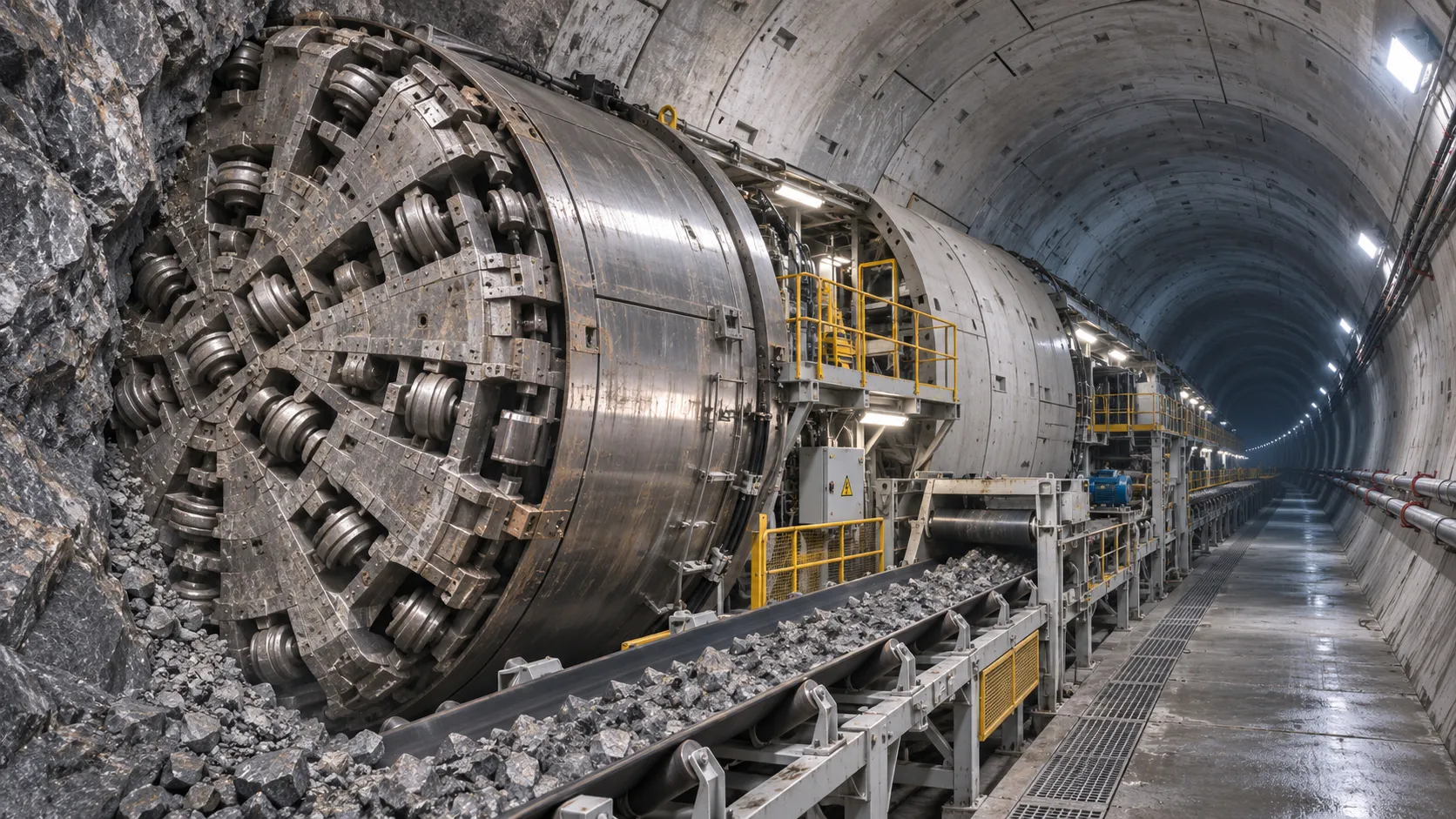
How TBM Excavation Works in Rock and Soft Ground: A Practical Guide
TBM Excavation in rock and soft ground explained: compare machine types, ground support, spoil removal, and the factors that guide smarter project planning.
Choosing a Zero-Emission Underground Equipment Supplier: What to Check
Choosing a zero emission underground equipment supplier? Compare duty-cycle performance, charging, safety, total costs and support before you commit.
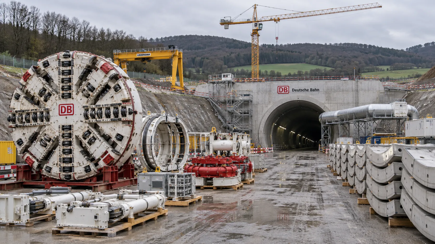
Construction Starts on Germany's Pfaffensteig Rail Tunnel, With Two TBMs Planned
Pfaffensteig rail tunnel construction is underway in Germany. Discover how two planned TBMs will support the 11-kilometre project near Stuttgart.
How Real-Time Underground Mapping Systems Work in Tunneling
Discover how real-time underground mapping systems guide tunneling teams, integrate sensor data, and support confident decisions with verified accuracy.
First Mechanized Tunnel Crossing Beneath the Panama Canal Completed
Panama Canal tunnel crossing: Explore the reported Metro Line 3 milestone and what it could mean for future underwater tunneling projects.
Underground Utility Construction Equipment: Choosing by Ground Conditions
Choose underground utility construction equipment with confidence. Compare trenching, HDD, microtunnelling and TBMs by ground conditions, risk and cost.

China Sets Tunnel Boring Machine Export Controls as India Pushes Local Production
China tunnel boring machine export controls could reshape procurement as India pushes local production. Explore potential supply and project impacts.
Choosing a Trenchless Pipeline Installation Contractor: Key Qualifications
Choose a trenchless pipeline installation contractor with confidence. Learn how to assess experience, equipment, safety, costs, and project risks before you hire.
China's 70% TBM Share and Export Controls Challenge India's Local Production
China's TBM export controls could challenge India's local production and infrastructure sourcing. Explore the potential risks and procurement options.
Related News
- 00
0000-00
How TBM Excavation Works in Rock and Soft Ground: A Practical Guide - 00
0000-00
Choosing a Zero-Emission Underground Equipment Supplier: What to Check - 00
0000-00
Construction Starts on Germany's Pfaffensteig Rail Tunnel, With Two TBMs Planned - 00
0000-00
How Real-Time Underground Mapping Systems Work in Tunneling - 00
0000-00
First Mechanized Tunnel Crossing Beneath the Panama Canal Completed
Weekly Insights
Stay ahead with our curated technology reports delivered every Monday.