
How to Evaluate Cutterhead Design Capabilities of Chinese TBM Manufacturers





How to Evaluate Cutterhead Design Capabilities of Chinese TBM Manufacturers
For a technical evaluator, cutterhead selection is rarely a matter of comparing face diameter, installed power, or the number of disc cutters shown in a brochure. The cutterhead is the interface between a TBM and an uncertain rock mass. Its geometry, stiffness, cutter mounting arrangement, opening ratio, wear protection, and maintainability all influence penetration, vibration, intervention frequency, and the consequences of a difficult geological transition.
This is especially relevant when assessing Cutterhead Design in China. Chinese manufacturers now cover a broad range of hard-rock, mixed-ground, slurry, earth-pressure-balance, and special-purpose TBM applications. Capability varies by supplier, project type, and design team. A credible evaluation therefore needs to move beyond a general question—“Has the manufacturer built a cutterhead of this size?”—and ask whether it can explain, document, manufacture, test, and support a cutterhead for the actual geology and operating constraints of the project.
The strongest technical review begins with the ground model, not the supplier shortlist. Rock strength, abrasivity, fracture condition, groundwater, expected fault zones, blockiness, plastic deformation risk, tunnel alignment, and access limitations should shape the cutterhead brief. If the employer’s geological baseline is incomplete, the tender should state how uncertainty will be managed rather than inviting bidders to offer an apparently optimized design based on assumptions that may not survive the first few hundred metres of excavation.
Start with the Design Logic, Not the Outer Shape
Two cutterheads can look similar from the front yet behave very differently underground. A useful manufacturer should be able to describe why each major design decision was made: cutter spacing, radial distribution, gage protection, center cutting arrangement, bucket geometry, spoke or plate configuration, and the location of wear-resistant components. “Proven design” is not enough on its own. Proven under which geology, machine diameter, thrust range, and muck removal arrangement?
For hard-rock machines, disc cutter layout deserves close scrutiny. The aim is not merely to fit the maximum possible number of cutters onto the face. Layout must support effective rock fragmentation while controlling individual cutter load, avoiding excessive overlap or undercutting, and maintaining reasonable access for replacement. The central area is often demanding because cutter paths are short and crushing action can dominate. At the periphery, gage cutters must maintain excavation profile while facing high side loads and substantial wear exposure.
Ask the manufacturer to provide the cutter layout drawing, cutter type and diameter assumptions, nominal load basis, spacing rationale, and the interface between cutterhead and main bearing. These documents do not need to reveal every proprietary calculation, but the supplier should be able to demonstrate a coherent engineering chain from geology to cutter selection, structural design, and operating envelope.
Mixed-face or highly variable ground raises a different set of questions. A cutterhead designed for intact competent rock can become inefficient when clay, seams, broken zones, or water-bearing material alter the muck flow and load pattern. Technical reviewers should examine whether the supplier has considered blockage, uneven face loading, overbreak risk, and the ability to adjust operating parameters. Where a project includes abrupt geological transitions, the cutterhead cannot be reviewed in isolation from the shield, probe drilling provisions, conditioning system, screw conveyor or slurry circuit, and cutter inspection strategy.

Structural Stiffness Is a Lifecycle Question
A cutterhead experiences concentrated cutter forces, torsional loading, bending, impact from boulders or blocky rock, and sometimes uneven loading across the face. Its structure must be sufficiently stiff to keep cutter mounts in their intended positions under working load. Excessive local deflection can affect cutting action and accelerate wear in mounts, bearings, fasteners, and adjacent structural members.
When evaluating Chinese TBM manufacturers, request a clear description of the structural verification process. This may include finite element analysis, load cases, material specifications, welding procedures, dimensional control, and inspection plans. The meaningful issue is not whether an analysis image exists in a presentation; it is whether the assumed loads reflect the project’s operating reality and whether the resulting design is connected to fabrication controls.
Reviewers should pay particular attention to transitions: spoke-to-rim joints, cutter box connections, discharge openings, lifting points, and interfaces with the drive system. These areas can combine stress concentration, welding complexity, and restricted inspection access. A supplier that can identify critical zones and explain how it manages them is generally more valuable than one that simply promises a heavier cutterhead. More steel does not automatically mean better durability; it can increase inertia, complicate transport, alter drive requirements, and make field repair harder.
What Evidence Should Be Requested?
Wear Protection Must Match the Failure Mode
Abrasive ground does not wear every part of a cutterhead equally. The outer rim, bucket lips, muck-flow paths, cutter housings, and areas close to openings may experience different combinations of sliding abrasion, impact, and material buildup. Technical teams should ask for a wear map rather than accepting a broad statement that the cutterhead uses “high wear-resistant material.”
The practical questions are straightforward. Which components are sacrificial? Can they be replaced or rebuilt without compromising the main structure? Are hardfacing and wear plates specified with a repair process? How are weld overlays controlled to reduce distortion or cracking risk? Is there enough clearance to remove a worn component in the confines of the machine? A wear solution that is difficult to inspect or renew may be unsuitable even if its material specification appears robust.
Disc cutter performance should also be treated as a system issue. Cutter ring material, bearing life, sealing, lubrication arrangement, mounting accuracy, cutterhead stiffness, and operational practice all affect consumption. It is reasonable to request the manufacturer’s recommendations for cutter monitoring and replacement, but avoid accepting projected cutter life as a contractual certainty unless the underlying geology and operating assumptions are explicitly agreed. Variability in rock mass condition can be decisive.
Look Closely at Muck Flow and Opening Design
Cutterhead openings are a compromise. Larger openings may improve the path for broken rock and reduce recirculation, but they also affect face support, structural continuity, and the behavior of material entering the machine. Smaller openings can strengthen a structure or suit certain support conditions, yet may encourage clogging where sticky fines, clay, or fibrous debris are present.
For each proposed configuration, ask how the manufacturer has considered the expected fragment size, cutterhead rotational speed, bucket loading, chamber conditions, and downstream transport system. This is particularly important for EPB and slurry machines, where cutterhead design interacts directly with pressure management and spoil conditioning. A supplier with genuine capability will not discuss openings as an isolated percentage; it will connect them to the complete excavation and muck-handling process.
Hard-rock TBMs also need a credible answer on boulder handling and oversize material. The answer may depend on the tunnel diameter, crusher arrangement, belt system, and anticipated geology. There is no universal best layout. What matters is whether the proposed design acknowledges the project-specific risk and defines the operating limits or contingency measures.
Manufacturing Capability Should Be Verified at the Factory
Cutterhead engineering can be sound on paper and still lose quality during fabrication. A factory review should therefore examine the route from plate preparation to machining, welding, inspection, trial assembly, and dispatch. For large-diameter equipment, dimensional accuracy at interfaces matters. Misalignment can complicate assembly and affect load distribution across the drive, cutterhead, and cutter mounts.
Technical evaluators should ask who owns the detailed design, who approves deviations, and how changes are documented. It is worth checking whether the manufacturer has in-house capability for critical machining and inspection, or whether key operations are subcontracted. Outsourcing is not automatically a weakness, but responsibilities, quality gates, and traceability should be clear.
Witness points should focus on meaningful milestones: material identification where required by the project, weld inspection, dimensional checks at key interfaces, cutter box installation, balancing or rotation checks where applicable, and trial fit-up with related components. The appropriate inspection scope depends on contract requirements and local standards, but the underlying principle is constant: the acceptance plan should test the risks identified during design review.
Maintenance Access Can Decide the Real Cost of a Design
A cutterhead should be judged not only by how it cuts, but by how it can be maintained when cutting becomes difficult. Cutter access is a major issue in hard-rock tunnelling and can become more consequential when interventions occur under pressure, in restricted space, or during schedule-critical sections. Review the proposed cutter-change method in realistic terms: working position, lighting, lifting aids, access openings, locking arrangements, tool clearance, and the training burden on site crews.
Ask for a maintenance narrative or sequence drawing. It should identify which cutters are accessible from inside the cutterhead, which may require intervention from the face, and what assumptions apply to ground stability or pressure. A design that reduces theoretical cutter changes but makes each intervention unusually difficult may not lower lifecycle risk.
Spare-part logic matters as well. Evaluate the interchangeability of cutter housings, wear blocks, fasteners, and specialist tooling. Confirm lead times and packaging arrangements for the project location. For international procurement, documentation quality, remote engineering response, and the ability to communicate design changes clearly can be as important as the component itself.
Use Reference Projects Carefully
Reference machines are useful, but only if they are compared intelligently. A large number of delivered TBMs does not prove that a particular cutterhead concept is suitable for a new alignment. Ask for references with comparable diameter, geology, groundwater condition, cutter type, tunnel length, and machine mode. Then examine what changed between the reference design and the proposed one.
The most useful reference discussion includes limitations: difficult strata encountered, cutterhead modifications made during manufacture or operation, lessons from wear behavior, and the basis for any design revision. A manufacturer willing to discuss engineering trade-offs is usually easier to work with than one presenting only idealized performance narratives.
At UTMD, cutterhead assessment is viewed within the wider mechanics of underground equipment. A TBM is often described as the aircraft carrier of tunnel construction because it combines mechanical, electrical, hydraulic, sensing, and segment-handling systems in a single operating platform. The same systems perspective is relevant across pipe jacking, drilling jumbos, underground LHD loaders, and mining haulage equipment: reliability is rarely determined by one component alone, but by how interfaces behave under real operating conditions.
A Better Basis for Supplier Comparison
When comparing Chinese TBM manufacturers, score the quality of their engineering response rather than only the proposed machine specification. Can they identify uncertainties in the ground data? Do they state design assumptions? Can they link cutter layout to structural loads, wear zones, muck flow, and maintenance access? Are design changes governed by a traceable process? Do factory inspection and site support plans address the same risks?
The preferred supplier is not necessarily the one offering the most elaborate cutterhead or the lowest initial cost. It is the one whose design can be interrogated, whose limitations are understood, and whose manufacturing and support processes give the project team a workable path when geology departs from expectation. Before award, require a project-specific cutterhead review using the latest geological information, agreed operating assumptions, inspection criteria, and a defined route for resolving design changes. That discipline provides a firmer basis for judging cutterhead design capability than any generic claim about market position.
Related News
How to Evaluate European Drill-and-Blast Tunnelling Contractors for Complex Projects
Drill and blast tunnelling contractors Europe: learn how to assess geology expertise, blast control, equipment reliability, safety, and programme resilience for complex projects.
Which Trenchless Construction Technique Fits Your Utility Crossing Conditions?
Trenchless construction techniques compared for utility crossings: choose HDD, microtunnelling, pipe jacking, or auger boring based on ground, accuracy, access, and risk.

What Is Driving Metro Tunnelling Demand Across Southeast Asia’s Major Cities?
Metro tunnelling Southeast Asia is accelerating as major cities tackle congestion, flooding, and connectivity. Explore the market forces, technical risks, and opportunities shaping demand.
Hard Rock Tunnelling in Australia: Selecting Methods for Variable Ground Conditions
Hard rock tunnelling in Australia: compare TBM, drill-and-blast and hybrid methods to manage variable ground, reduce risk and protect project costs.
Hydropower Tunnel Excavation: Selecting Methods for Variable Rock Conditions
Hydropower tunnel excavation methods for variable rock conditions: compare TBM, drill-and-blast, and hybrid strategies to improve safety, progress, and project control.
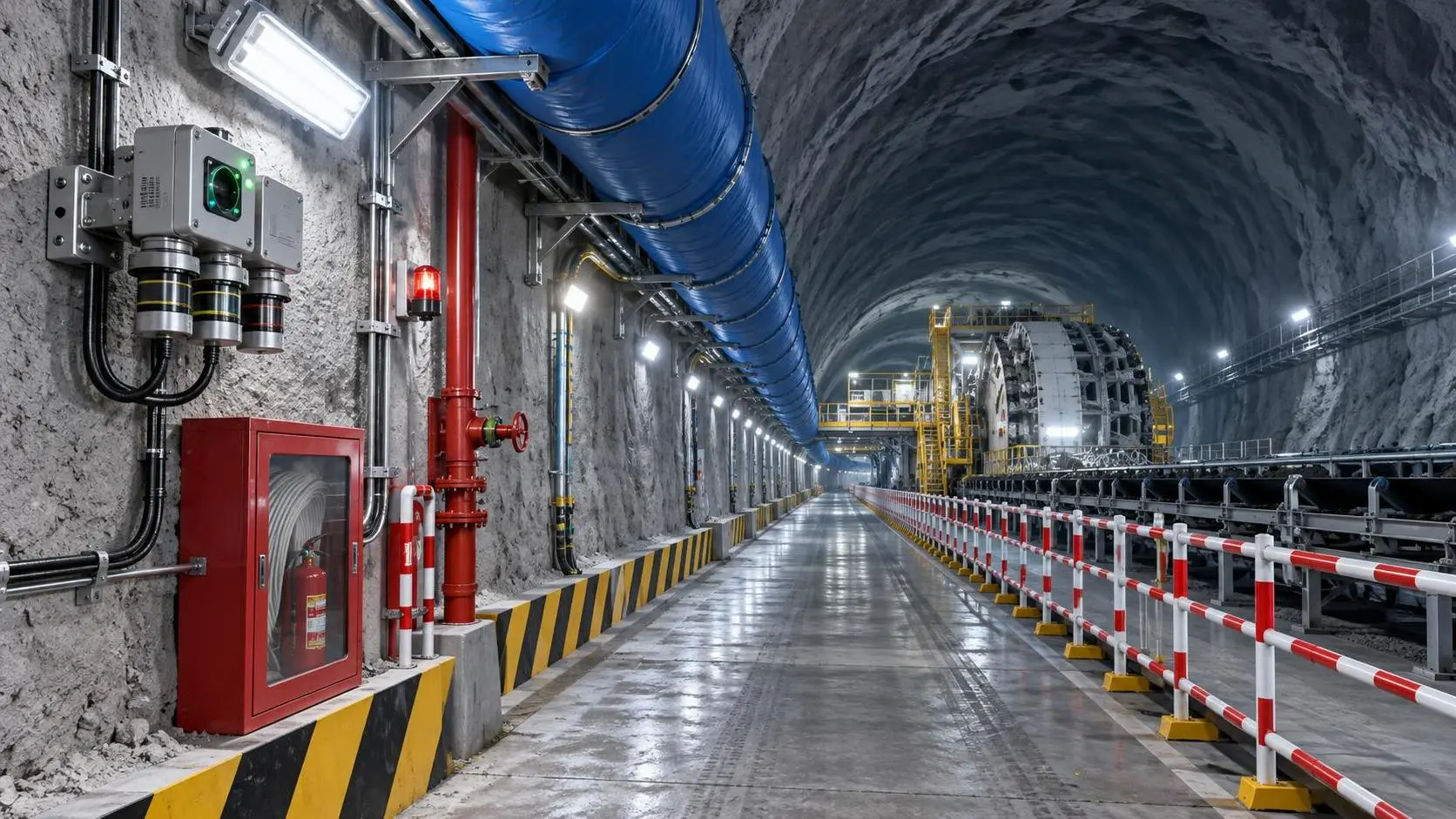
How to Select Underground Safety Equipment for Tunnelling by Hazard and Work Zone
Underground Safety Equipment for tunnelling: match protection to hazards, work zones, compliance, and emergency needs with this practical selection guide.
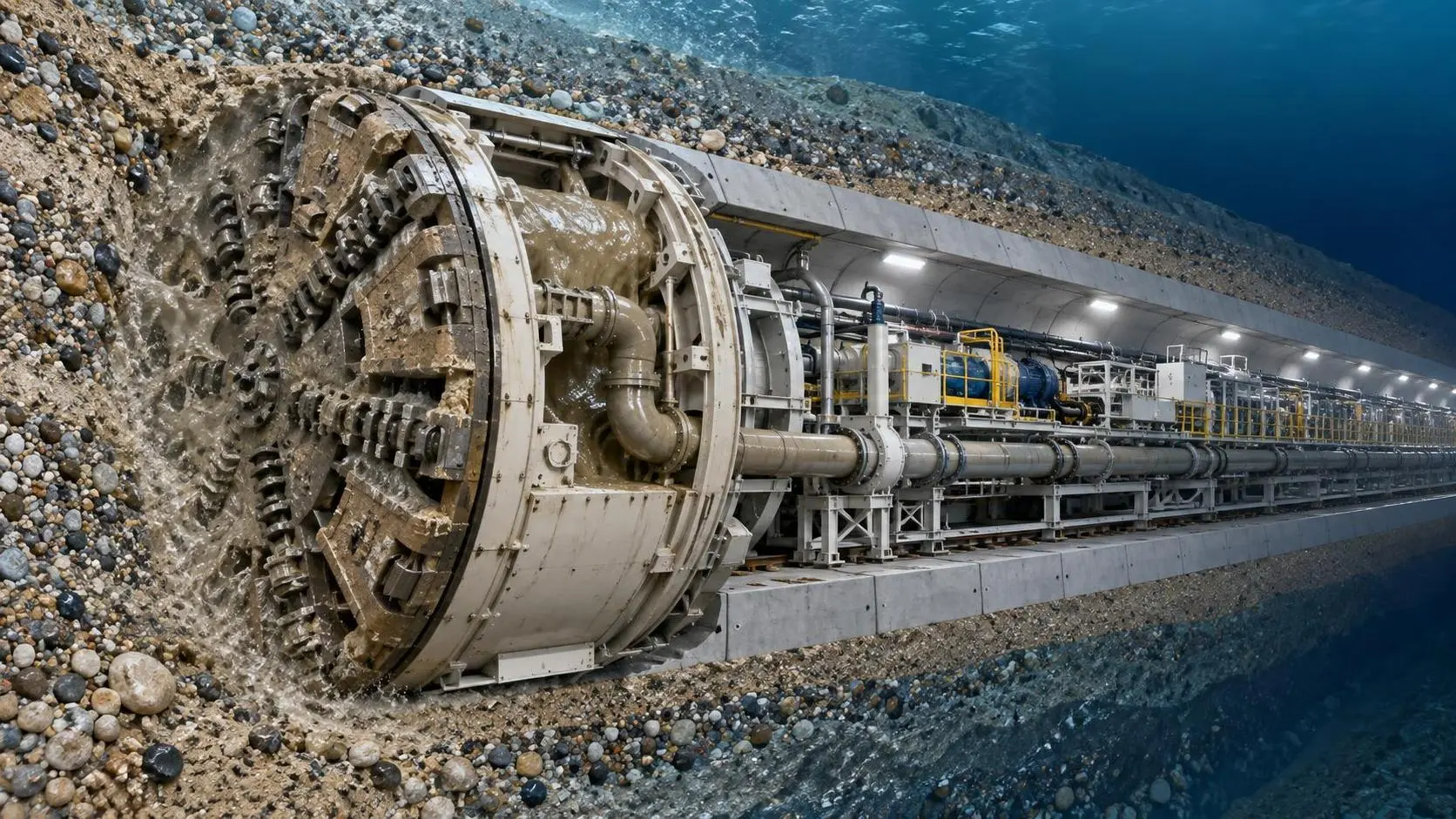
EPB or Slurry Shield? Selecting Soft-Ground Tunnelling Equipment by Soil Conditions
Tunnel Excavation Equipment for soft ground: compare EPB and slurry shields by soil, groundwater, settlement risk, and project logistics to choose confidently.
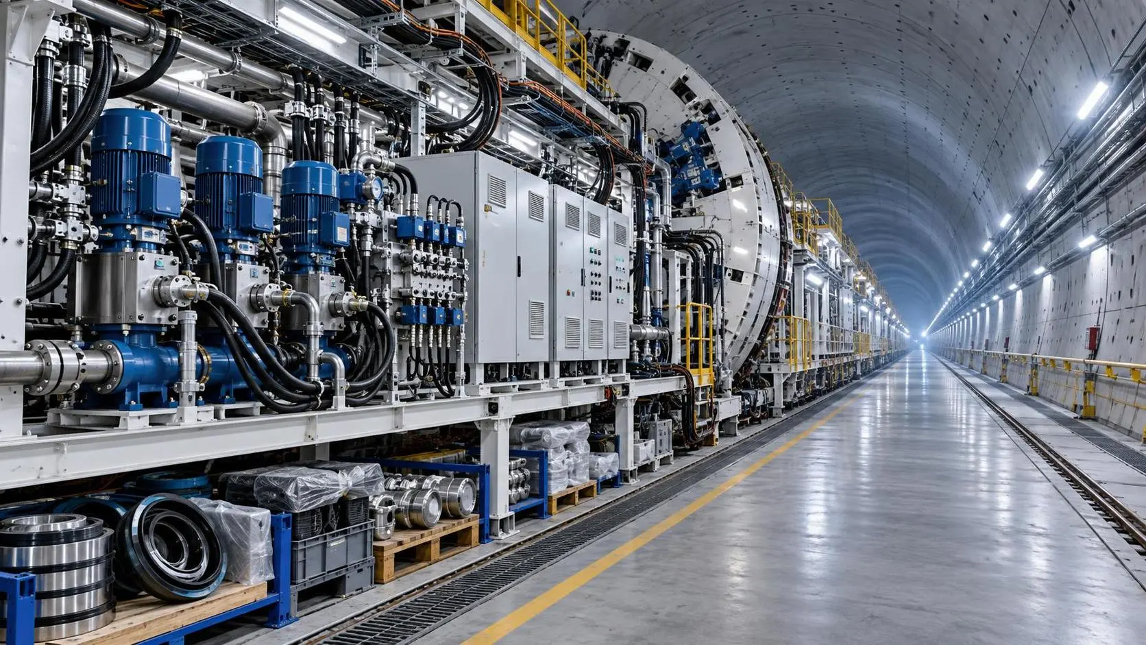
How to Specify TBM Backup System Parts for Reliable Long-Distance Tunnelling
TBM backup system parts: learn how to specify reliable spares for long-distance tunnelling, reduce downtime, ensure compatibility, and speed underground recovery.
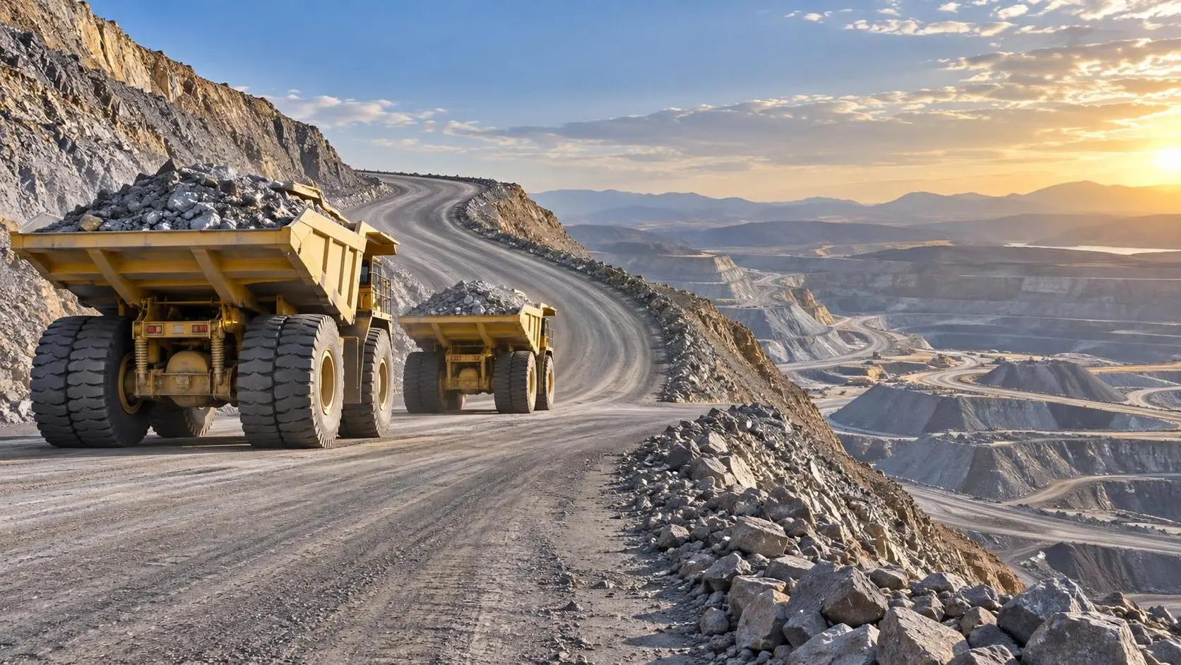
How to Size Open Pit Mining Trucks for Haul Distance, Grade, and Payload?
Open Pit Mining Trucks: learn how to match payload, haul distance, grade, road resistance, and loading capacity for safer, lower-cost mine operations.
Related News
- 00
0000-00
How to Evaluate European Drill-and-Blast Tunnelling Contractors for Complex Projects - 00
0000-00
Which Trenchless Construction Technique Fits Your Utility Crossing Conditions? - 00
0000-00
What Is Driving Metro Tunnelling Demand Across Southeast Asia’s Major Cities? - 00
0000-00
Hard Rock Tunnelling in Australia: Selecting Methods for Variable Ground Conditions - 00
0000-00
Hydropower Tunnel Excavation: Selecting Methods for Variable Rock Conditions
Weekly Insights
Stay ahead with our curated technology reports delivered every Monday.