
Selecting Underground Rock Bolting Equipment for Variable Ground Conditions





Selecting rock bolting equipment for underground mining starts with the ground-support design, not with the drill feed or carrier size. A bolter that performs well in competent, uniform rock can become slow, inaccurate, or unsafe when the heading encounters fractured zones, weak contacts, water-bearing seams, or changing excavation profiles. The equipment must reliably install the specified bolt system in the least favorable sections likely to be encountered, while remaining productive in routine ground.
The most useful evaluation question is therefore not, “What is the strongest bolter available?” It is: “Can this machine install the required bolts, at the required angle and pattern, within the available space, while controlling exposure and maintaining quality when the ground changes?” That question connects rock mass conditions, support design, operating method, and lifecycle requirements into one decision.
Start with the support system, then define the machine
Rock bolting equipment should be matched to the complete support method. This includes bolt type, bolt length, hole diameter, installation angle, resin or grout system, mesh requirements, and the sequence in which support must be installed after excavation. A mismatch between the bolter and the support design is often more damaging than a modest difference in drilling rate.
For example, a conventional mechanical bolter may be suitable where short bolts are installed in predictable roof conditions and access is straightforward. It may be a poor fit where long cable bolts, split sets, friction bolts, resin capsules, mesh, straps, or mixed support patterns are required in the same cycle. In those conditions, the evaluator should look beyond basic drilling capability and assess rod handling, consumable storage, bolt insertion, resin charging, grouting provision, and operator protection as one system.
Support design can also change during mine development. If geological mapping indicates that headings may transition from competent host rock into faulted or highly jointed ground, selecting a machine only for the initial conditions can create an avoidable bottleneck later. A bolter with practical adjustment range, suitable feed travel, and the ability to support more than one bolt-installation method may carry a higher initial cost but reduce disruption when ground classes change.
Translate variable ground into equipment requirements
“Variable ground” is not a single condition. Each type of variability affects equipment selection differently. Hard, abrasive rock places demands on drill steel, shank components, drifter performance, flushing, and maintenance access. Fractured rock may cause hole collapse, drill deviation, poor anchorage, and loose material at the face. Weak or squeezing ground can reduce available clearance and make rapid support installation more important than high nominal penetration rate. Water can interfere with hole cleaning, resin installation, electrical systems, and corrosion control.
Before comparing machines, define the expected range of conditions by excavation area. The objective is not to produce a geological report inside the procurement process; it is to identify the conditions that alter the bolting cycle.
- Competent, abrasive rock: prioritize reliable drilling energy, robust consumable handling, effective flushing, and maintainable drifter and feed components.
- Jointed or blocky ground: prioritize drilling control, accurate collaring, boom stability, hole cleaning, and rapid installation under supported areas.
- Weak, broken, or ravelling ground: prioritize protected operator positioning, short exposure time, mesh and strap capability, and support installation close to the face.
- Water-bearing ground: assess sealing, drainage management, drilling-fluid control, compatibility with the selected anchoring system, and corrosion implications for permanent support.
- Mixed ground on one level: prioritize configuration flexibility and a workflow that does not require extensive machine conversion between headings.
Ground conditions also affect how much precision is needed. In a stable drift, a small variation in hole collar position may have limited practical consequence. In highly fractured ground, incorrect bolt spacing, inadequate embedment, or poor installation angle can leave local zones unsupported. The machine’s boom geometry, feed alignment, positioning controls, and visibility therefore deserve the same attention as impact power.

Excavation geometry can rule out an otherwise capable bolter
Underground bolting machines operate in constrained spaces, and dimensions on a specification sheet do not fully describe whether a machine can work efficiently at the site. Evaluate the actual heading profile, turning radii, crosscuts, gradient, ventilation arrangements, service lines, passing bays, and interaction with loaders, trucks, and scaling equipment.
Reach should be assessed at every required bolt position, not simply at maximum boom extension. Roof-edge bolts, shoulder bolts, sidewall bolts, and upward-angled holes can each expose limitations in boom articulation or feed rotation. A carrier may technically reach the crown but require repeated repositioning to complete the pattern. That adds cycle time, increases traffic conflict, and can compromise consistent collar placement.
Low-profile mines require particular scrutiny. A compact carrier is useful only when its operator compartment, canopy or cabin, feed, drill steel, and bolt magazine can all function within the available height. Conversely, selecting a large multi-boom unit for a small heading may reduce installation time per round but create congestion that slows the overall development cycle.
For projects with several excavation sizes, a single standardized bolter may still be the right choice, but only if the machine has meaningful reach and profile flexibility. Standardization reduces training, spares complexity, and maintenance variation. It should not force crews to accept poor access at the headings where support quality matters most.
Compare installation capability, not just drilling capacity
Drilling is only one part of a bolting cycle. The cycle also includes positioning, collaring, hole drilling, flushing, installing resin or grout where applicable, inserting the bolt, tensioning or setting it, placing plates and nuts, and often installing mesh or straps. In poor ground, scaling and face preparation can add further delay. A procurement comparison based only on metres drilled per minute misses where production time is actually lost.
Automation changes this comparison further. Automated boom positioning, drilling control, and digital pattern guidance can improve repeatability where headings follow a defined geometry and crews can maintain the supporting processes around the machine. They are less valuable if the operation cannot maintain survey references, communication coverage, clean working areas, or disciplined data handling. Automation should be evaluated as an operating system, not as an isolated feature list.
Operator exposure and dust control are selection criteria
A rock bolting machine is part of the ground-control process, so operator protection needs to be evaluated alongside output. Broken ground, unsupported shoulders, falling fragments, drill steel handling, resin handling, and mesh placement all create exposure points. A protected cabin, canopy arrangement, remote control option, or automated handling feature has the greatest value when it removes a real exposure from the planned cycle.
Dust control also deserves a practical review. Drilling generates fine dust in confined underground workplaces, and effective collection depends on more than the presence of a collector. The system must be appropriately integrated with drilling parameters, flushing method, filter maintenance, hose routing, and the site ventilation plan. A dust system that restricts access, blocks visibility, or is difficult to maintain may be bypassed in daily operation. The better choice is the arrangement crews can use consistently without compromising drilling accuracy or machine availability.
Look for reliability where the machine will actually fail
Lifecycle evaluation should focus on the components and interfaces most likely to interrupt the bolting cycle: drifter and feed wear parts, hydraulic hoses, seals, boom pins, electrical connectors, dust-collection filters, bolt-handling mechanisms, sensors, and control-system diagnostics. The relevant question is not whether a machine has a long feature list. It is whether routine inspection, fault finding, and component replacement are realistic in the mine’s maintenance model.
Consider where maintenance will occur, what lifting aids are available, whether trained technicians are present underground, and how quickly critical parts can be supplied. A highly automated bolter may be justified in a mature operation with digital maintenance capability and predictable parts support. In a remote or rapidly changing project, a simpler but robust configuration with accessible service points may offer better sustained utilization.
Energy and ventilation constraints should be evaluated at the same time. Diesel-powered equipment affects heat, emissions, and ventilation demand; battery-electric equipment can reduce local exhaust emissions but changes charging, battery handling, electrical infrastructure, and shift-planning requirements. The right powertrain depends on the mine’s infrastructure and traffic pattern, not on a generic preference for one technology.
Use a site-based trial plan before finalizing the purchase
Factory demonstrations rarely reproduce underground constraints. A credible evaluation plan uses representative headings, expected bolt patterns, typical consumables, and realistic ground-support sequencing. Include normal ground and, where feasible, a section that reflects more difficult conditions. Measure the complete cycle rather than drilling time alone: positioning, drilling, installation, support coverage, consumable changes, operator intervention, dust-control use, maintenance actions, and recovery from routine interruptions.
The trial should also test interfaces. Can the bolter work around the planned haulage cycle? Does mesh handling interfere with ventilation ducting? Can survey and geology teams access the face without disrupting support? Does the machine produce usable installation records in the site’s existing systems? These issues determine whether a technically capable machine becomes a productive part of the development process.
A practical decision sequence
- Confirm the bolt design, support classes, and the most demanding credible ground conditions.
- Map each required bolt position against the actual excavation profile and access constraints.
- Define the full installation cycle, including mesh, straps, resin or grout, and quality checks.
- Set exposure-control requirements for operators and nearby crews before comparing automation options.
- Assess maintenance capability, parts support, power supply, ventilation, and data infrastructure.
- Run representative trials and compare complete-cycle performance, installation quality, and downtime response.
For underground mining and tunnelling teams following equipment developments, UTMD’s coverage of drilling jumbos and underground operating systems can help frame rock bolting within the wider excavation, haulage, electrification, and automation workflow. That wider view matters because the bolter does not operate alone: its effectiveness depends on how well it fits the advancing face and the support process surrounding it.
The final selection should make difficult ground manageable without imposing unnecessary complexity in normal headings. A machine that consistently reaches the pattern, installs the specified support, protects the crew, and can be maintained within site conditions will usually deliver more value than one selected solely for maximum drilling performance.
Related News
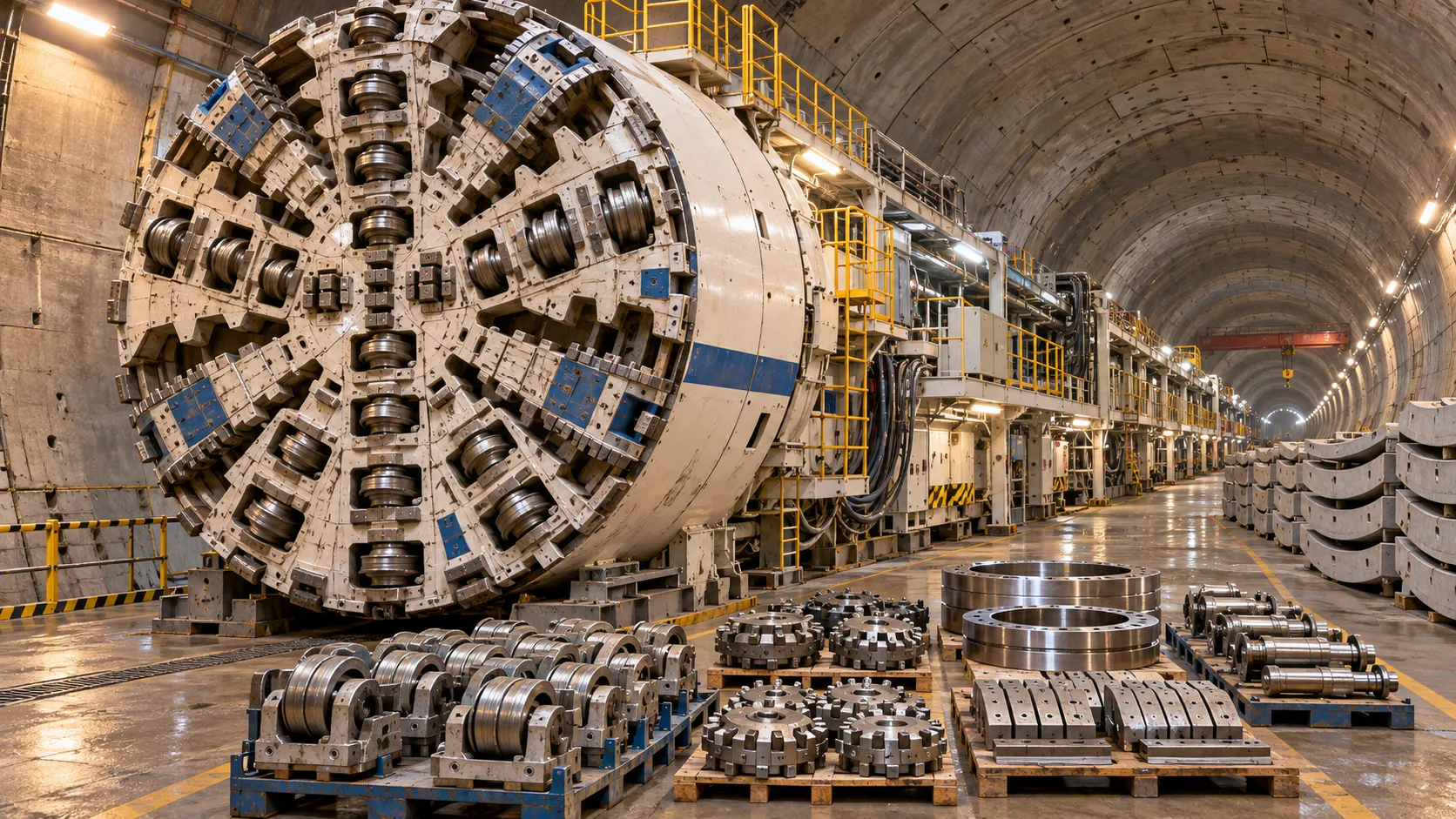
China's TBM Export Controls Prompt Infrastructure Concerns in India
China's TBM export controls could affect infrastructure projects in India. Explore potential supply risks and practical procurement steps.
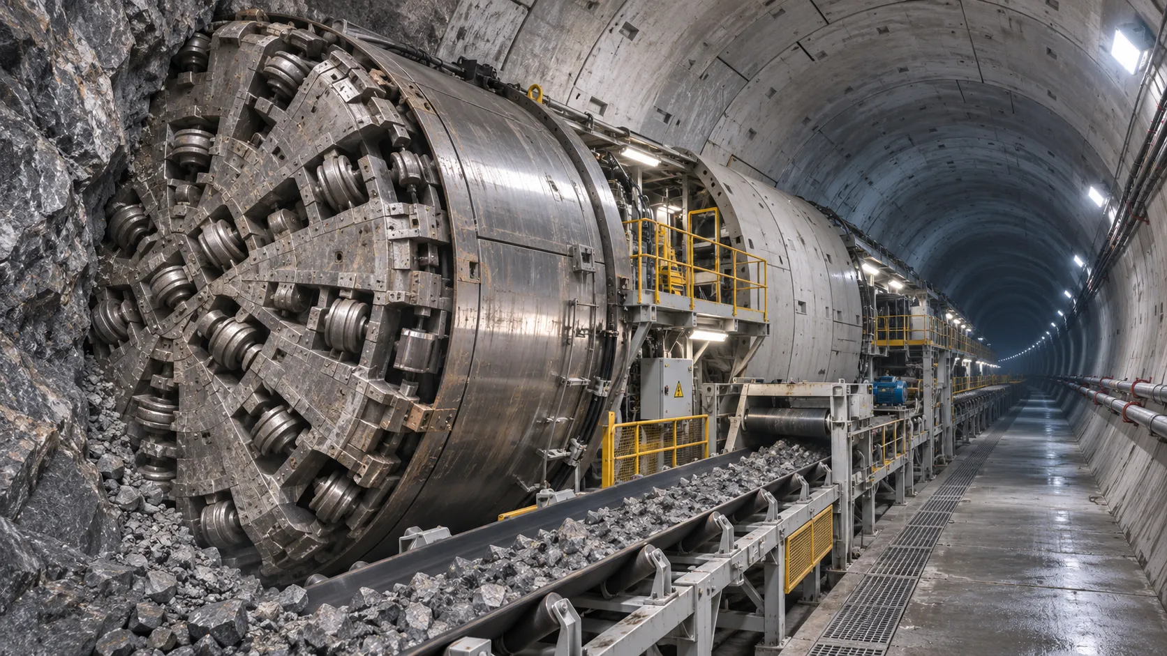
How TBM Excavation Works in Rock and Soft Ground: A Practical Guide
TBM Excavation in rock and soft ground explained: compare machine types, ground support, spoil removal, and the factors that guide smarter project planning.
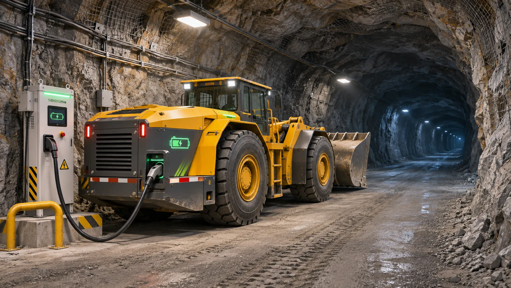
Choosing a Zero-Emission Underground Equipment Supplier: What to Check
Choosing a zero emission underground equipment supplier? Compare duty-cycle performance, charging, safety, total costs and support before you commit.
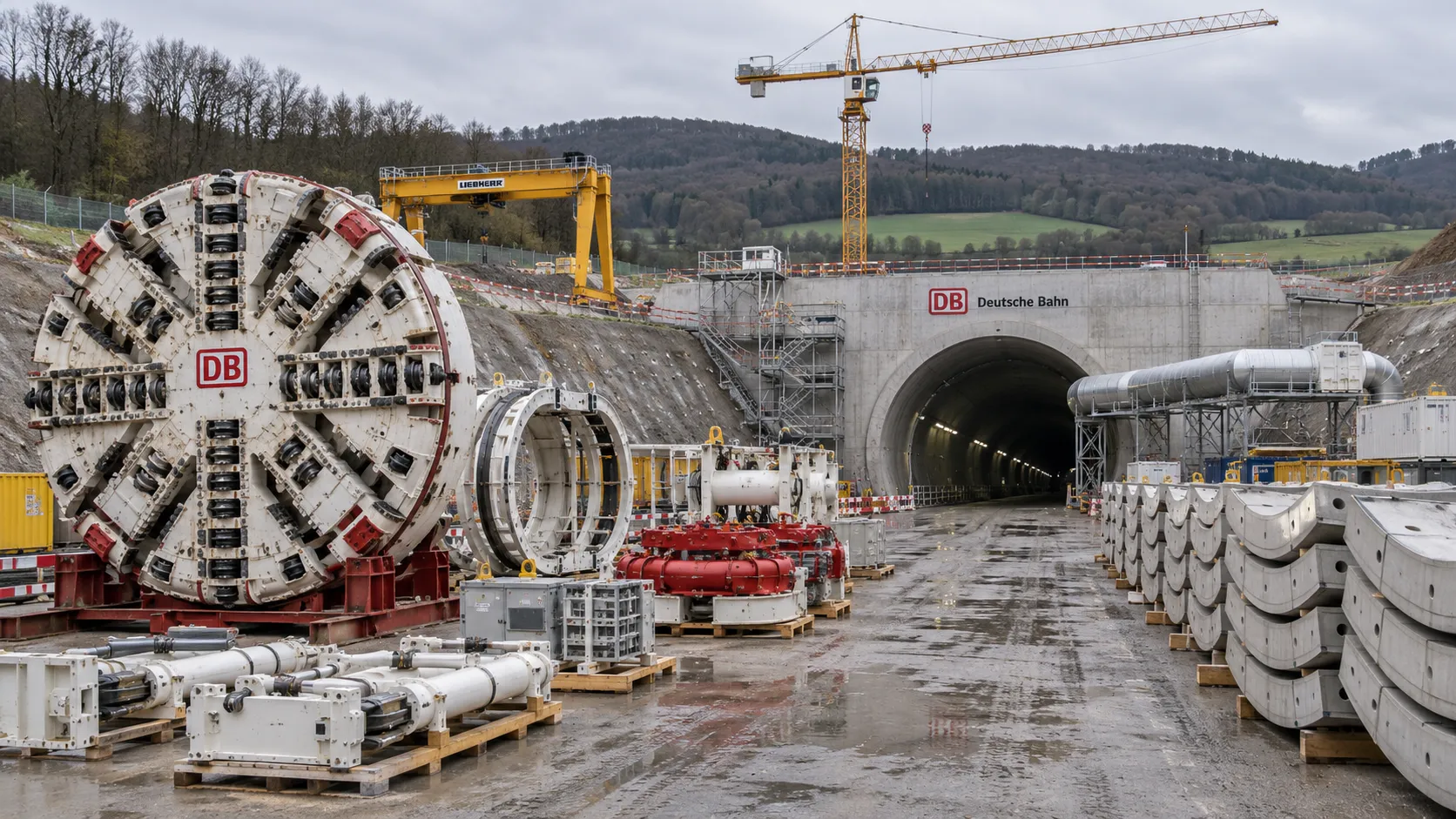
Construction Starts on Germany's Pfaffensteig Rail Tunnel, With Two TBMs Planned
Pfaffensteig rail tunnel construction is underway in Germany. Discover how two planned TBMs will support the 11-kilometre project near Stuttgart.
How Real-Time Underground Mapping Systems Work in Tunneling
Discover how real-time underground mapping systems guide tunneling teams, integrate sensor data, and support confident decisions with verified accuracy.
First Mechanized Tunnel Crossing Beneath the Panama Canal Completed
Panama Canal tunnel crossing: Explore the reported Metro Line 3 milestone and what it could mean for future underwater tunneling projects.
Underground Utility Construction Equipment: Choosing by Ground Conditions
Choose underground utility construction equipment with confidence. Compare trenching, HDD, microtunnelling and TBMs by ground conditions, risk and cost.
China Sets Tunnel Boring Machine Export Controls as India Pushes Local Production
China tunnel boring machine export controls could reshape procurement as India pushes local production. Explore potential supply and project impacts.
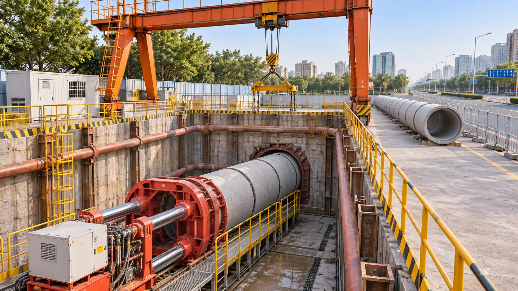
Choosing a Trenchless Pipeline Installation Contractor: Key Qualifications
Choose a trenchless pipeline installation contractor with confidence. Learn how to assess experience, equipment, safety, costs, and project risks before you hire.
Related News
- 00
0000-00
China's TBM Export Controls Prompt Infrastructure Concerns in India - 00
0000-00
How TBM Excavation Works in Rock and Soft Ground: A Practical Guide - 00
0000-00
Choosing a Zero-Emission Underground Equipment Supplier: What to Check - 00
0000-00
Construction Starts on Germany's Pfaffensteig Rail Tunnel, With Two TBMs Planned - 00
0000-00
How Real-Time Underground Mapping Systems Work in Tunneling
Weekly Insights
Stay ahead with our curated technology reports delivered every Monday.