
Rock Bolting Standards Explained: Load Testing, Installation Rules, and Compliance Checks





Why do rock bolting standards matter so much underground?
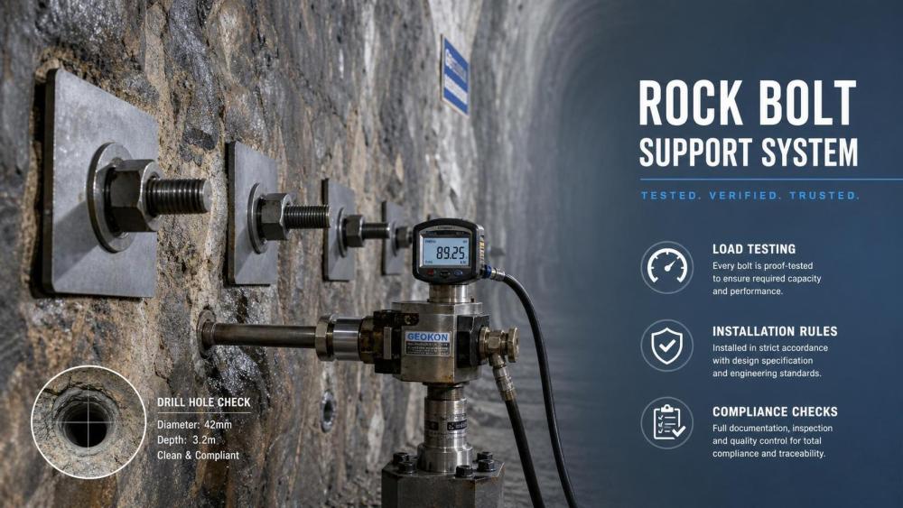
Rock bolting standards sit at the center of underground safety, support reliability, and inspection discipline.
In tunnelling, mining, and trenchless works, a bolt is never just a fastener. It is part of a ground support system that must perform under changing stress, vibration, water, and production pressure.
That is why rock bolting standards focus on more than strength values alone. They also address drilling accuracy, resin or grout control, plate seating, torque, pull testing, documentation, and ongoing compliance checks.
A useful way to read these standards is to ask one practical question: can this support system be installed consistently, verified clearly, and trusted over time?
Across the underground sector, that question now matters even more. High-output TBM headings, drill-and-blast development, pipe jacking shafts, and deep mine access drives all depend on predictable support quality.
UTMD often tracks this wider shift. As underground equipment becomes more automated, electrified, and data-driven, support standards also need tighter measurement and cleaner evidence.
In other words, rock bolting standards are not isolated paperwork. They connect geotechnical intent, field execution, and asset-level risk control in harsh underground environments.
When people refer to rock bolting standards, what are they really checking?
Most searches for rock bolting standards are really searches for acceptance criteria.
The standard may come from a national code, project specification, mine ground control plan, or client inspection procedure. Yet the field questions tend to be very similar.
Typical checks include the following points:
- bolt type matches the approved support design
- hole diameter and depth suit the bolt and anchorage medium
- drilling angle and spacing stay within tolerance
- resin mixing time or grout quality meets the procedure
- torque, tension, or preload is verified where required
- load testing is sampled at the right frequency
- records are complete enough for audit and traceability
Some sites treat these items as separate checks. The better approach is to view them as one chain. A compliant test result means little if the hole was over-drilled or the resin spin time was wrong.
This is also where confusion often starts. One project may specify torque-controlled friction bolts. Another may require fully grouted rebars with proof loading. The phrase rock bolting standards sounds universal, but compliance is always system-specific.
So the first discipline is simple: confirm the support class, bolt family, test method, and acceptance limit before work starts.
A quick reference for the checks that usually matter most
The table below helps separate what is being checked from why it matters in practice.
How should load testing be interpreted instead of just recorded?
Load testing is one of the most searched parts of rock bolting standards because it looks objective. A number appears on a gauge, and the bolt either passes or fails.
In reality, good interpretation is more demanding.
A proper proof test checks whether the installed bolt can sustain a specified load without unacceptable movement or loss of anchorage. Depending on the project, the method may involve pull testing, tensioning checks, or periodic destructive validation.
The first point to confirm is test intent. Is the site trying to verify design capacity, installation quality, or day-to-day workmanship control? Those are related, but not identical.
The second point is timing. Resin bolts tested too early can produce misleading results. Cement-grouted bolts tested before full cure can fail the schedule rather than the support design.
Then comes displacement. A bolt that reaches target load with excessive movement may still reveal weak bonding, hole enlargement, or poor plate seating. Reading only the final load number can hide that problem.
More disciplined teams usually watch four things together:
- applied load versus required proof load
- movement during loading and hold period
- failure mode, if the test does fail
- repeatability across shifts, headings, and crews
That last point is easy to miss. One passed test does not confirm stable process control. A cluster of marginal results in one heading may indicate drilling deviation, consumable issues, or changing ground conditions.
This is where modern underground operations are moving. The same data culture used for TBM cutter wear, jumbo drilling accuracy, or battery equipment uptime is now being applied to support verification as well.
Which installation rules usually decide whether a compliant bolt will actually perform?
Most support failures are not caused by a missing standard. They come from installation drift.
A bolt can be fully compliant on paper and still underperform because the hole was too wide, the resin was not mixed properly, or the plate never seated against the rock.
In practical terms, rock bolting standards become real through a few critical field controls.
Drilling accuracy is not a minor detail
Hole position, angle, and depth affect bond length and support geometry. In fractured ground, small drilling errors can place a bolt outside the intended load path.
That risk increases when drilling jumbos operate at speed or where visibility is poor after blasting or scaling.
Anchorage materials need environmental control
Resin cartridges react differently under heat, cold, or water. Grout quality changes with mix ratio, pumping distance, and waiting time. Standards often assume these variables are controlled. The heading may prove otherwise.
Plate and nut condition still matter
Loose contact, distorted plates, or damaged threads can reduce confinement even when the anchor itself is sound. This is especially important in dynamic ground or high-vibration production zones.
Shift-to-shift consistency should be monitored
Installation quality often changes with crew experience, consumable supply, and equipment condition. Trend checks are often more revealing than isolated inspections.
What are the most common compliance gaps, even on disciplined projects?
The common gaps are rarely dramatic. They are small breaks in control that accumulate.
One frequent issue is assuming a supplier certificate replaces field verification. Material conformity matters, but rock bolting standards still require installation and performance evidence.
Another weak point is test frequency. Sites sometimes reduce sampling after early good results. That can miss deterioration caused by bit wear, changing geology, or rushed cycles.
Documentation gaps are also common. Missing location references, unclear bolt IDs, and incomplete cure times make later audits difficult. More importantly, they make failure investigation slower.
There is also a subtle compliance problem in mixed fleets. When headings use different jumbos, bolt rigs, or consumable brands, crews may carry over one method into another system. That creates hidden variation.
A practical watchlist usually includes:
- uncalibrated test equipment
- expired or poorly stored resin and grout materials
- unverified changes in bolt pattern or spacing
- inspection records completed after the shift from memory
- pass criteria copied from another project without geotechnical review
The deeper lesson is that compliance checks should not be treated as a closing activity. They work best when tied to drilling, installation, and support mapping in near real time.
How can rock bolting standards be turned into a workable site checklist?
A useful checklist is short enough to be used and strict enough to catch drift.
In practice, the most effective format follows the support cycle rather than the document structure of the standard.
Before drilling, confirm the current support class, approved bolt type, hole layout, and material batch status.
During drilling, check collar position, hole depth, bit condition, flushing, and visible deviation.
During installation, verify resin count or grout volume, mixing or pumping method, insertion depth, plate contact, and torque or tension where specified.
After installation, record cure timing, conduct scheduled load tests, tag the location clearly, and review exceptions before the next round advances.
For projects adopting digital inspection, this process fits naturally with broader underground intelligence workflows. That matters in the same ecosystems UTMD follows, where equipment automation and support quality increasingly share one operating picture.
Rock bolting standards only add value when they can be translated into repeatable field behavior. The best next step is to compare the written standard against actual heading practice, then tighten the points where testing, installation, and records stop aligning.
That review does not need to start with a major redesign. Start with one bolt type, one heading, one test method, and one checklist. Once the evidence is reliable, scaling compliance becomes much easier.
Related News
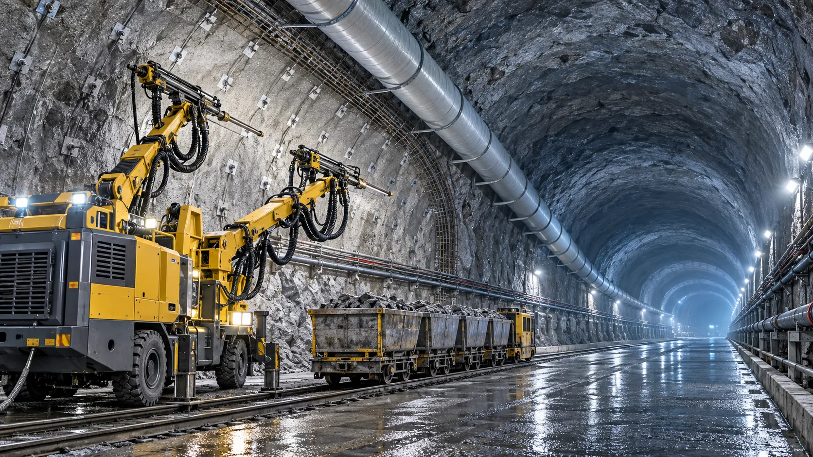
How to Evaluate European Drill-and-Blast Tunnelling Contractors for Complex Projects
Drill and blast tunnelling contractors Europe: learn how to assess geology expertise, blast control, equipment reliability, safety, and programme resilience for complex projects.
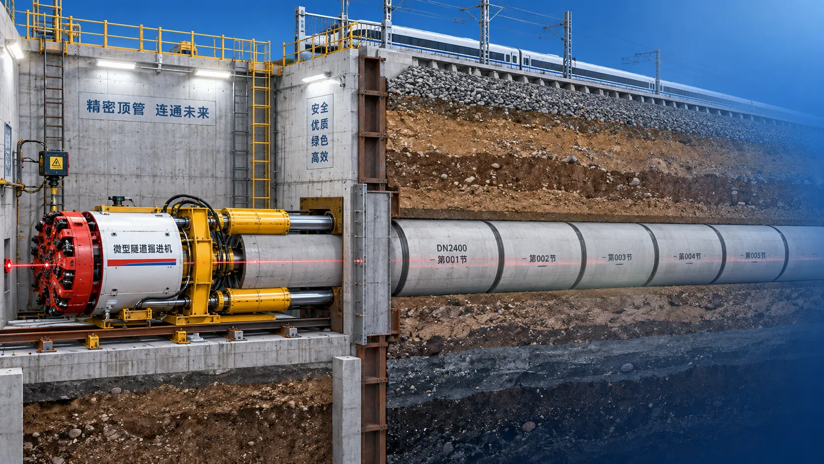
Which Trenchless Construction Technique Fits Your Utility Crossing Conditions?
Trenchless construction techniques compared for utility crossings: choose HDD, microtunnelling, pipe jacking, or auger boring based on ground, accuracy, access, and risk.
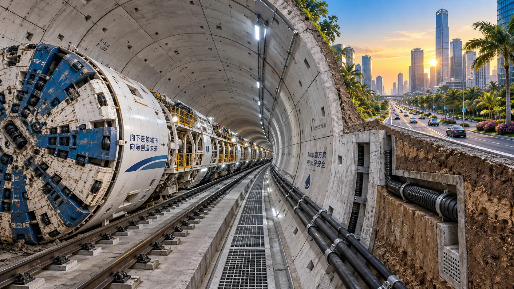
What Is Driving Metro Tunnelling Demand Across Southeast Asia’s Major Cities?
Metro tunnelling Southeast Asia is accelerating as major cities tackle congestion, flooding, and connectivity. Explore the market forces, technical risks, and opportunities shaping demand.
Hard Rock Tunnelling in Australia: Selecting Methods for Variable Ground Conditions
Hard rock tunnelling in Australia: compare TBM, drill-and-blast and hybrid methods to manage variable ground, reduce risk and protect project costs.
Hydropower Tunnel Excavation: Selecting Methods for Variable Rock Conditions
Hydropower tunnel excavation methods for variable rock conditions: compare TBM, drill-and-blast, and hybrid strategies to improve safety, progress, and project control.
How to Select Underground Safety Equipment for Tunnelling by Hazard and Work Zone
Underground Safety Equipment for tunnelling: match protection to hazards, work zones, compliance, and emergency needs with this practical selection guide.
EPB or Slurry Shield? Selecting Soft-Ground Tunnelling Equipment by Soil Conditions
Tunnel Excavation Equipment for soft ground: compare EPB and slurry shields by soil, groundwater, settlement risk, and project logistics to choose confidently.
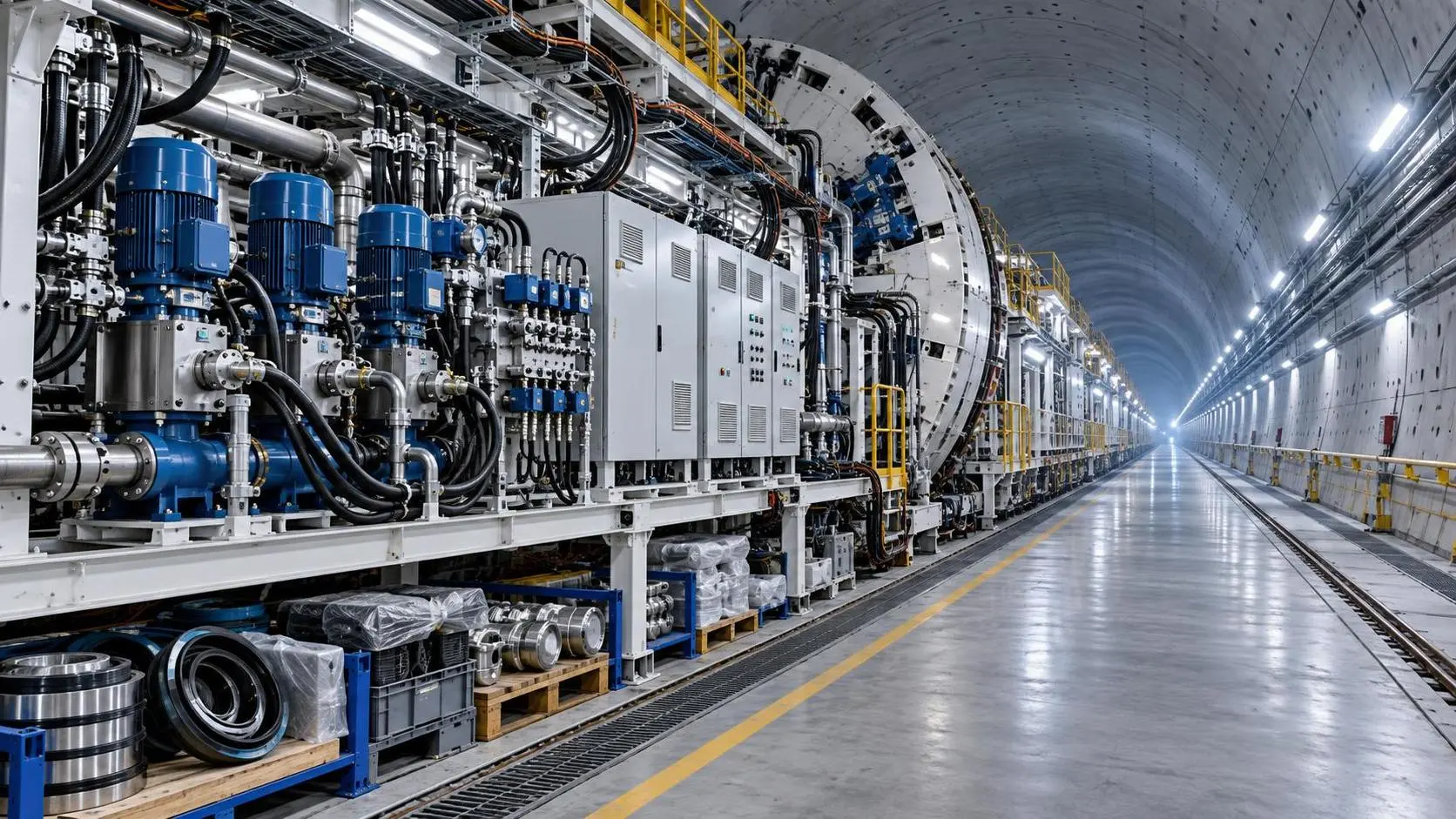
How to Specify TBM Backup System Parts for Reliable Long-Distance Tunnelling
TBM backup system parts: learn how to specify reliable spares for long-distance tunnelling, reduce downtime, ensure compatibility, and speed underground recovery.
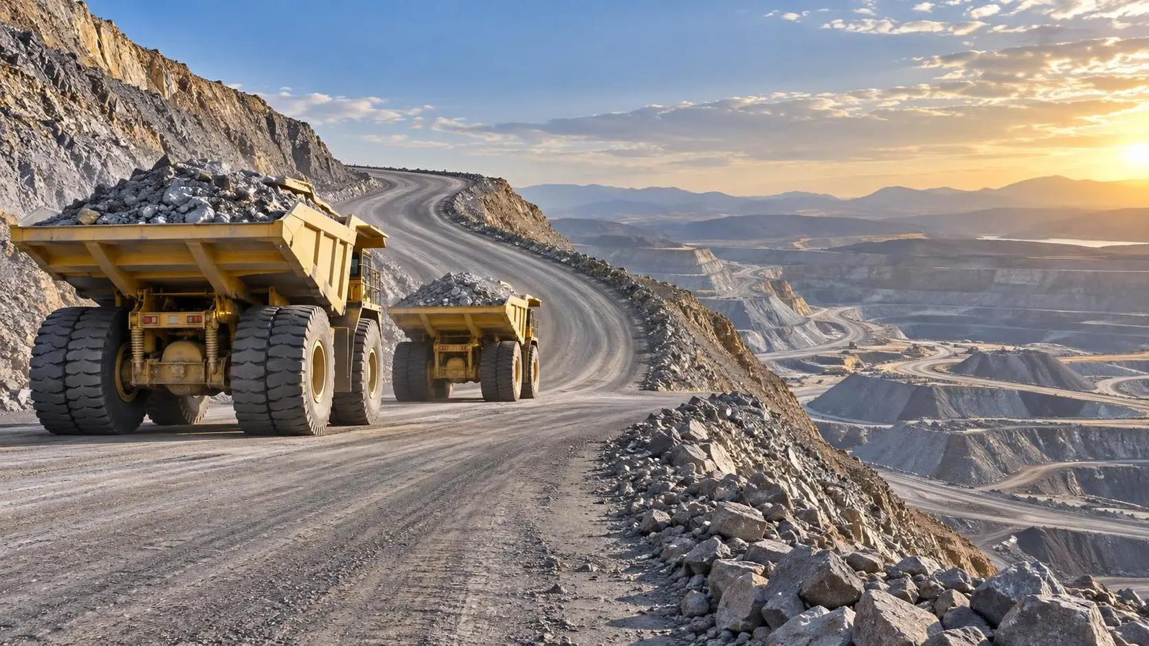
How to Size Open Pit Mining Trucks for Haul Distance, Grade, and Payload?
Open Pit Mining Trucks: learn how to match payload, haul distance, grade, road resistance, and loading capacity for safer, lower-cost mine operations.
Related News
- 00
0000-00
How to Evaluate European Drill-and-Blast Tunnelling Contractors for Complex Projects - 00
0000-00
Which Trenchless Construction Technique Fits Your Utility Crossing Conditions? - 00
0000-00
What Is Driving Metro Tunnelling Demand Across Southeast Asia’s Major Cities? - 00
0000-00
Hard Rock Tunnelling in Australia: Selecting Methods for Variable Ground Conditions - 00
0000-00
Hydropower Tunnel Excavation: Selecting Methods for Variable Rock Conditions
Weekly Insights
Stay ahead with our curated technology reports delivered every Monday.