
How to Evaluate Tunnel Cutterhead Manufacturers for Mixed-Ground TBM Projects





A mixed-ground drive can change from competent rock to abrasive sand, clay, boulders, or a pressurized water-bearing interface within a short distance. In that setting, a cutterhead that looks adequate on a general specification sheet may become the source of excessive tool changes, unstable face support, high torque peaks, or a planned intervention that cannot safely be completed. The practical question is not which supplier offers the most features; it is whether the proposed cutterhead is engineered for the ground transitions, machine constraints, and maintenance access of the actual alignment.
When evaluating a tunnel cutterheads manufacturer, start with evidence of geology-specific engineering rather than nominal diameter, steel grade, or cutter count alone. A capable manufacturer should be able to explain how the face layout, cutter tools, openings, wear protection, drive interface, and intervention strategy work together under changing conditions. The evaluation should move from ground model to operating envelope, then to manufacturability and field support.
Begin with the ground model, not the catalog
Mixed ground is not one condition. It may describe alternating hard rock and soft soil, fractured rock with clay seams, rock blocks embedded in granular material, or transitions between permeable and impermeable layers. Each condition creates different demands on the cutterhead. A design that breaks rock efficiently may clog in sticky fines; a highly open design that allows spoil flow in soft ground may reduce face support or admit oversized blocks that damage internal components.
Before requesting a technical proposal, prepare a ground-condition package that goes beyond broad geological labels. It should identify likely transition zones, rock strength ranges, abrasivity indicators where available, groundwater pressure, boulder risk, fines content, plasticity of cohesive soils, expected muck behavior, and the degree of uncertainty between boreholes. Also include the required excavation mode, planned chamber pressure, alignment curvature, depth, TBM diameter, and restrictions on intervention.
A manufacturer should respond to this information with questions. A proposal prepared without clarification of pressure regime, expected rock-block size, allowable chamber opening geometry, or disc-cutter access is usually too generic for a high-risk mixed-ground application. Engineering discussions should reveal how the supplier interprets uncertainty, not merely how it handles idealized ground descriptions.
Assess whether the cutterhead architecture fits the excavation mode
The cutterhead must match both geology and the TBM’s intended operating method. For slurry, earth-pressure-balance, hard-rock, or hybrid configurations, the acceptable balance between opening ratio, spoke geometry, tool arrangement, and mixing capability differs substantially. In mixed ground, the main challenge is often preserving stable material flow while maintaining enough structural strength for localized impact loading.
Ask the manufacturer to define the operating range assumed for the design. The answer should cover expected face pressure, cutterhead rotational speed range, torque range, permissible muck size, and the mechanism used to move excavated material into the chamber or intake. A meaningful response connects these factors. For example, cutterhead openings should not be discussed separately from the anticipated soil conditioning, chamber behavior, and risk of cobbles bridging at the intake.
The table is not a scoring formula. It helps expose where a proposal is based on engineered assumptions and where it relies on broad claims. A design can have a reasonable opening ratio and still perform poorly if openings are located where sticky material accumulates, where large fragments enter unpredictably, or where structural members obstruct material movement.
Look beyond cutter quantity to the complete tool system
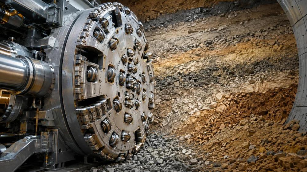
Technical reviewers often compare the number and diameter of disc cutters first. Those values matter, especially in rock-bearing sections, but they do not establish suitability on their own. The tool system includes disc cutters, scrapers, ripper tools, carbide bits, bucket lips where applicable, gauge tools, wear bars, and protection at vulnerable transition zones. The right combination depends on whether the cutterhead must excavate hard inclusions, condition soil, resist abrasion, or limit clogging.
Request a tool map showing each tool type, location, and intended function. The manufacturer should explain how the design controls track overlap across the face, protects the center and periphery, and addresses the higher loads often seen at the gauge. On variable ground, the ability to exchange or reconfigure selected tools can be as important as the original layout. This does not mean every cutterhead needs a fully modular arrangement; it means that the supplier should identify which changes are feasible, when they can be performed, and what operational trade-offs they introduce.
Wear protection deserves separate review. Mixed ground can combine abrasive minerals with impact from hard fragments, so a single hard-facing approach may not suit every zone. Ask where wear plates, carbide protection, replaceable blocks, or sacrificial elements are used, and how their wear state can be inspected. The critical issue is whether protection preserves the cutterhead’s geometry long enough to avoid exposing structural steel or changing material-flow behavior.
Questions that reveal tool-system maturity
- Which tools are expected to carry the highest load in the predicted transition zones?
- How is the center area protected from poor cutting action or material buildup?
- What is the replacement approach for gauge tools under restricted access?
- Which wear components can be changed independently, and which require major disassembly?
- How will operators distinguish normal wear from damage that could affect cutterhead balance or face excavation?
Verify torque, thrust, and fatigue margins against the TBM envelope
A cutterhead manufacturer should not size the structure only for a nominal machine torque. Mixed-ground drives can create uneven loading: one part of the face may be cutting rock while another passes through weaker soil, or isolated blocks may create impact events. These conditions produce local stresses and fluctuating torque that are more relevant than a single steady-state value.
Ask for the load cases used in the structural assessment. The documentation does not need to disclose proprietary calculation details, but it should state the relevant assumptions: torque and thrust limits, eccentric loading, tool reaction forces, possible blockage loads, pressure loads where applicable, and fatigue cycles. Review how loads transfer from the cutterhead body to the main drive connection. Weld details, bolted interfaces, flange geometry, and local reinforcements are not minor fabrication details; they determine whether repeated variable loading remains manageable.
Compatibility with the existing or planned TBM is equally important. Confirm bolt pattern, interface dimensions, maximum mass, center-of-gravity assumptions, drive torque limit, permissible rotational speed, seal arrangement, and available hydraulic or mechanical provisions. A technically sound cutterhead that imposes unacceptable mass or inertia on the drive system creates a different reliability problem.
Examine sealing, pressure integrity, and contamination paths
Where pressurized excavation is involved, cutterhead design cannot be evaluated separately from sealing and access arrangements. Water, fines, abrasive slurry, and conditioned soil can migrate through gaps or damaged interfaces. Once contamination reaches bearings, tool housings, drive-side cavities, or inspection spaces, the consequences may extend beyond cutter wear.
The manufacturer should identify sealing interfaces and explain how they are protected during normal rotation, transient torque, tool replacement, and pressure changes. Review the relationship between cutterhead openings, chamber pressure, back-loading on tools, and access procedures. If the cutterhead includes internal cavities or wear-resistant components attached by fasteners, ask how those features are protected from loosening, abrasive ingress, and hidden wear.
Do not accept “pressure capable” as a complete answer. The meaningful questions are: pressure at which location, under what operating state, with what maintenance condition, and with what inspection method? The same discipline applies to any purge, lubrication, flushing, or monitoring arrangement associated with the cutterhead system.
Test the manufacturer’s intervention and service assumptions
Mixed ground is often difficult because the operating condition changes faster than maintenance windows can be created. A manufacturer’s field-service capability should therefore be assessed as part of the design review. The issue is not whether technicians are available in principle, but whether the supplier can support diagnosis, spare-part identification, tool-change planning, and design clarification when wear patterns differ from expectations.
Ask for a recommended spare-parts scope tied to the proposed configuration. It should distinguish between high-consumption tools, critical wear parts, seals, fasteners, and components whose lead time could affect recovery from damage. Review whether the supplier provides part identification that remains usable after equipment has accumulated abrasion and contamination. Clear drawings, traceable part numbers, tightening requirements, and replacement instructions matter during a pressured maintenance decision.
Intervention planning should be realistic. Some tools may be replaceable only under specific ground-support or pressure conditions. Others may require access from the chamber, a planned shutdown, or additional safety controls. A credible manufacturer states these boundaries directly instead of implying that every tool can be changed quickly in every operating state.
Compare proposals using traceability, not presentation quality
A polished proposal can hide important gaps. Build a comparison record that links each supplier response to the same project requirement. Give greater weight to evidence that can be checked: cutterhead drawings, tool maps, interface drawings, stated load cases, wear-protection details, inspection access, spare-parts lists, manufacturing controls, and proposed acceptance checks.
Manufacturing quality should be reviewed through the parts most exposed to failure consequences: large weldments, critical machined interfaces, tool-holder attachment zones, balancing requirements, and dimensional control at the main-drive connection. Ask how the manufacturer controls distortion after welding, verifies critical geometry, manages nonconforming parts, and records the final configuration. The goal is not to demand every internal procedure; it is to establish that the delivered cutterhead will match the approved design rather than an approximate version of it.
It is also useful to separate design questions from commercial assumptions. A lower initial offer may omit spare tools, replaceable wear components, on-site support, documentation depth, or contingency options for a changing geology. Those omissions can be material even when the base cutterhead appears equivalent.
Use a structured technical review before award
The final review should bring together geology, TBM engineering, operations, maintenance, and procurement rather than allowing each function to approve a different part of the proposal. Start with the most severe credible ground transition, then test whether the cutterhead can handle it without creating an unacceptable intervention or drive-load risk. Next, examine the most likely wear mechanism and confirm that inspection and replacement are practical.
- Confirm that all suppliers received the same ground and machine information.
- Identify design assumptions that differ between proposals, especially opening ratio, pressure regime, tool mix, and maximum block size.
- Review the face layout and tool tracks against likely rock, soil, and mixed interfaces.
- Check structural and interface compatibility against the TBM’s documented operating limits.
- Evaluate service scope, critical spares, and intervention restrictions alongside the equipment price.
- Record unresolved uncertainties and determine whether they require additional geological data, machine-interface verification, or a revised cutterhead concept.
The strongest selection is rarely the proposal with the longest feature list. It is the one whose assumptions are visible, whose limitations are acknowledged, and whose design choices can be traced back to the expected mixed-ground behavior. That standard gives evaluators a practical basis for choosing a cutterhead manufacturer that supports controlled excavation rather than adding uncertainty to an already variable underground drive.
Related News
How to Evaluate European Drill-and-Blast Tunnelling Contractors for Complex Projects
Drill and blast tunnelling contractors Europe: learn how to assess geology expertise, blast control, equipment reliability, safety, and programme resilience for complex projects.
Which Trenchless Construction Technique Fits Your Utility Crossing Conditions?
Trenchless construction techniques compared for utility crossings: choose HDD, microtunnelling, pipe jacking, or auger boring based on ground, accuracy, access, and risk.

What Is Driving Metro Tunnelling Demand Across Southeast Asia’s Major Cities?
Metro tunnelling Southeast Asia is accelerating as major cities tackle congestion, flooding, and connectivity. Explore the market forces, technical risks, and opportunities shaping demand.
Hard Rock Tunnelling in Australia: Selecting Methods for Variable Ground Conditions
Hard rock tunnelling in Australia: compare TBM, drill-and-blast and hybrid methods to manage variable ground, reduce risk and protect project costs.
Hydropower Tunnel Excavation: Selecting Methods for Variable Rock Conditions
Hydropower tunnel excavation methods for variable rock conditions: compare TBM, drill-and-blast, and hybrid strategies to improve safety, progress, and project control.
How to Select Underground Safety Equipment for Tunnelling by Hazard and Work Zone
Underground Safety Equipment for tunnelling: match protection to hazards, work zones, compliance, and emergency needs with this practical selection guide.
EPB or Slurry Shield? Selecting Soft-Ground Tunnelling Equipment by Soil Conditions
Tunnel Excavation Equipment for soft ground: compare EPB and slurry shields by soil, groundwater, settlement risk, and project logistics to choose confidently.
How to Specify TBM Backup System Parts for Reliable Long-Distance Tunnelling
TBM backup system parts: learn how to specify reliable spares for long-distance tunnelling, reduce downtime, ensure compatibility, and speed underground recovery.

How to Size Open Pit Mining Trucks for Haul Distance, Grade, and Payload?
Open Pit Mining Trucks: learn how to match payload, haul distance, grade, road resistance, and loading capacity for safer, lower-cost mine operations.
Related News
- 00
0000-00
How to Evaluate European Drill-and-Blast Tunnelling Contractors for Complex Projects - 00
0000-00
Which Trenchless Construction Technique Fits Your Utility Crossing Conditions? - 00
0000-00
What Is Driving Metro Tunnelling Demand Across Southeast Asia’s Major Cities? - 00
0000-00
Hard Rock Tunnelling in Australia: Selecting Methods for Variable Ground Conditions - 00
0000-00
Hydropower Tunnel Excavation: Selecting Methods for Variable Rock Conditions
Weekly Insights
Stay ahead with our curated technology reports delivered every Monday.