
TBM Disc Cutter Design: Key Geometry and Load Factors for Hard Rock Tunnelling





Geometry and load capacity must be evaluated as one system
For hard rock tunnelling, a disc cutter cannot be assessed simply by its diameter, bearing rating, or advertised wear life. The cutter must create sufficient compressive stress beneath the rock surface to initiate cracks, while the cutterhead and main drive must supply that force repeatedly without excessive heat, abnormal vibration, or uneven consumption across the face.
That is why tbm disc cutter design should be reviewed as a cutterhead-system question. A larger cutter may accept higher normal load, but it also changes torque demand, mounting space, cutterhead mass, and the consequences of a seized bearing. A narrow tip can improve penetration in competent rock, yet may become vulnerable to edge damage where joints, abrasive inclusions, or alternating lithologies dominate. The preferred design is therefore the one that matches the expected rock mass and the machine's usable thrust and torque envelope, not the cutter with the highest standalone rating.
For technical evaluators, the practical objective is to establish whether cutter geometry, spacing, mounting, and load allocation can sustain the planned excavation rate under realistic ground variability. The review should also identify what happens when conditions depart from the design assumption, because most costly cutter problems emerge in transition zones rather than in homogeneous laboratory-grade rock.
Disc diameter sets the load range, but not the cutting outcome by itself
Disc diameter is commonly treated as the first design choice because it strongly influences allowable normal force, contact conditions, bearing size, and ring volume available for wear. Larger discs generally provide more structural capacity and a larger wear allowance. They are often attractive where high-strength, massive rock requires substantial thrust to generate productive chip formation.
However, diameter is not a universal proxy for performance. Increasing diameter raises the radial position of the cutter contact point and can increase cutterhead torque demand. It may also require a larger mounting envelope, constrain the arrangement of adjacent cutters, and complicate access for inspection or replacement. In a machine already limited by installed torque or by cutterhead structural capacity, a move to a larger disc may shift the bottleneck rather than remove it.
The relation between diameter and rock fragmentation also depends on the rock mass. In intact hard rock, a sufficiently loaded disc can form crushed zones and induce lateral cracks that link with the fracture zones created by neighbouring cutters. In heavily fractured ground, the same large disc may not achieve the expected chip-forming mechanism because pre-existing discontinuities govern breakage. Applying high loads without considering that change can increase ring impact damage, bearing shock, and face instability risk without delivering a corresponding gain in penetration.
A design review should therefore ask three connected questions:
- Can the cutter ring and bearing assembly withstand the anticipated normal load, rolling speed, and thermal environment?
- Can the cutterhead, main bearing, and drive system transmit the aggregate force and torque at the intended penetration rate?
- Will the rock mass create chips between adjacent cutter paths, or will discontinuities and mixed ground alter the breakage mechanism?
Those questions are more useful than selecting a disc size from rock strength alone. Uniaxial compressive strength remains a useful input, but it does not fully capture abrasivity, grain interlocking, brittleness, joint orientation, groundwater effects, or the frequency of lithological transitions.
Tip width and ring profile govern stress concentration and wear behaviour
The cutter ring transfers load into a narrow contact zone. Tip width, edge radius, ring hardness, and heat-treatment quality influence how efficiently that load creates rock failure and how quickly the ring loses its intended profile. The familiar trade-off is straightforward: a narrower tip concentrates force more effectively, while a wider contact area can distribute stress and offer greater robustness against local damage.
In competent hard rock, an excessively wide tip can reduce contact stress and force the machine to apply more thrust before productive cracking begins. The result may be lower penetration, greater rubbing, and elevated thermal loading. Conversely, a very narrow or sharp profile can be less tolerant of impact loading, embedded hard minerals, and abrupt contact with blocky or uneven ground. The cutter may still show acceptable average wear, yet suffer local spalling, edge chipping, or abnormal flat formation that accelerates replacement.
Ring material selection must be considered alongside geometry. Hardness supports abrasion resistance, but a ring designed solely for maximum hardness can sacrifice toughness needed to survive impact and uneven loading. The relevant engineering balance depends on the expected failure mode. Highly abrasive but comparatively uniform rock calls for attention to controlled wear and retained profile. Mixed or fractured geology puts greater emphasis on toughness, crack resistance, and the ability to tolerate intermittent shock.
Wear should not be evaluated only as millimetres of radial loss. As a disc ring wears, its contact geometry changes. The cutter may require more force to maintain the same penetration, produce more frictional heat, and alter the interaction with neighbouring cuts. A cutter population can therefore lose efficiency before every individual ring reaches its nominal replacement limit. Monitoring systems and maintenance criteria should account for profile condition, uneven wear, seal condition, bearing response, and rotation quality rather than relying on diameter loss alone.

Spacing determines whether the rock chips or merely crushes
Cutter spacing is one of the most consequential parameters in a hard-rock cutterhead. It defines the distance between adjacent cutter paths and therefore affects whether cracks from one indentation interact with the next. When spacing, penetration, and normal load are appropriately matched, the rock between cuts can break away as chips. When they are poorly matched, much of the machine energy is consumed in localized crushing and grinding.
Spacing cannot be fixed sensibly without considering expected penetration per revolution. A cutterhead designed around a particular penetration range may perform poorly when operational constraints keep penetration well below that range. At low penetration, cutters may not develop enough crack interaction to produce efficient chipping. Operators may respond by increasing thrust, but higher force at inadequate penetration can increase rubbing and cutter load without materially improving breakage.
At the other extreme, spacing that is too close for the achievable penetration can create redundant cutting paths and excessive cutter count. This may raise the number of bearings, seals, mounts, and inspection points exposed to failure. It can also complicate cutterhead layout while offering limited benefit in the dominant geology. A high cutter count is not automatically a high-performance configuration; it is an operating and maintenance commitment that must be justified by the rock conditions and face geometry.
Spacing should also vary across the cutterhead where the cutting mechanics differ. Gauge cutters work under different constraints from central cutters. They are responsible for maintaining excavation diameter and interact with the face at a more oblique geometry. Their exposure to side loading, overbreak, and wear patterns may require a distinct arrangement and robust mounting approach. Centre cutters face lower rolling velocity but can experience difficult initiation conditions, while outer cutters cover longer paths and can accumulate wear rapidly. A technically credible layout does not assume every cutter station carries the same duty.
Load distribution is where a sound drawing becomes a reliable cutterhead
A cutterhead design may contain suitable individual cutters yet still fail operationally if loads are not distributed plausibly across the face. The total thrust generated by the TBM is divided unevenly among cutter positions according to geometry, rock contact, penetration, face irregularity, and local ground conditions. Design calculations must reflect peak and transient loads, not only average force per cutter.
Three load categories deserve separate attention. Normal load drives indentation and crack formation. Rolling load is associated with cutter rotation and face interaction. Side load occurs when the cutter is forced laterally by uneven rock, steering corrections, joint-controlled breakage, or cutterhead deflection. Disc cutters are principally designed for rolling contact under high normal force; persistent side loading is particularly damaging because it can overload bearings, seals, and mounts in ways that are not visible from a simple thrust calculation.
Load distribution must remain credible when the face is not perfectly flat. Local high spots can overload a small group of cutters, while voids or weak zones can unload others. Cutterhead stiffness, cutter mounting compliance, and the control of advance parameters all influence how severe this redistribution becomes. Evaluators should look for evidence that the design has considered realistic face topography and geological variability rather than only an idealized circular cutting plane.
Mounting and bearing design often decide maintenance risk
Disc cutter reliability is not determined by the ring alone. Bearings, seals, lubrication arrangement, housing strength, and mounting interfaces operate in an abrasive, wet, high-load environment. A cutter that no longer rotates properly can slide across the face, generating rapid flat wear and heat. Once that condition develops, the cutter can increase drag and impose abnormal forces on surrounding stations.
Seal performance is especially important where groundwater, fine abrasive particles, or pressurized face conditions can contaminate the cutter assembly. A seal arrangement must be assessed for the actual ingress risk, not only for nominal operating conditions. The technical review should also examine how early bearing degradation will be detected. Temperature, vibration, rotation resistance, grease condition, and wear inspection may all contribute, depending on the cutter system and machine instrumentation.
Replacement procedures belong in the design evaluation because cutter change time affects TBM availability as directly as nominal cutter life. The relevant question is not simply whether a cutter can be replaced, but whether replacement remains practical at heavily worn gauge positions, in restricted access zones, and under the site’s ventilation, lifting, and safety constraints. A design that requires frequent but fast, controlled replacement may be preferable to one with a theoretically longer interval but difficult intervention conditions.
How to review a cutter design against a hard-rock excavation programme
A useful technical assessment starts with a geological envelope rather than a single representative rock strength. The envelope should distinguish intact rock properties from rock-mass structure and identify abrasive minerals, joint sets, faulted zones, transition boundaries, groundwater conditions, and the likelihood of mixed-face operation. These factors determine whether the dominant threat is slow penetration, abrasive ring loss, impact damage, bearing contamination, excessive vibration, or repeated interventions.
The cutterhead proposal can then be tested against the machine envelope: available thrust, torque, power, rotational speed, permissible cutterhead deflection, and thermal limits. This step should clarify the operating window in which the proposed geometry is expected to work efficiently. If productive cutting depends on force or torque close to the machine’s continuous limit, there is little allowance for cutter wear, muck-related drag, local hard bands, or steering corrections.
Finally, the maintenance model should be tied to cutter station duty rather than an undifferentiated average life estimate. Inspect expected consumption by cutter zone, criteria for preventive replacement, access method, spare inventory logic, and consequences of a seized or damaged cutter remaining in service. That approach exposes whether the assumed advance rate is operationally achievable over a campaign, rather than merely possible during favorable ground.
Hard-rock tunnelling rewards cutter systems that maintain controlled crack formation with manageable loads over changing geology. The strongest technical decision is rarely based on a single disc size, ring grade, or nominal bearing capacity. It comes from demonstrating that cutter geometry, spacing, station duty, thrust, torque, and maintenance access remain compatible when rock conditions become less uniform than the initial design case.
Related News

Tunnel Boring Machine Costs: Budgeting for Purchase, Operation, and Project Risk
Tunnel Boring Machines cost more than purchase price. Learn how to budget lifecycle costs, downtime, logistics, wear, and project risk for smarter TBM decisions.

Open-Pit Haulage Cost Analysis: How Mine Managers Can Cut Cost per Tonne
Open pit haulage cost analysis: discover practical ways to reduce cost per tonne through payload control, cycle-time optimization, road performance, and smarter fleet decisions.

Tunnel Construction Innovations That Reduce Risk and Schedule Delays on Urban Projects
Tunnel construction innovation for urban projects: discover smarter TBMs, real-time monitoring, trenchless methods, and automation that reduce risk and protect schedules.

Hydraulic Tipping Stability Risks in Multi-Axle Dump Special Trailers
Dump special trailers: discover key hydraulic tipping stability risks, multi-axle load dynamics, and practical safety controls for safer, smarter bulk hauling.
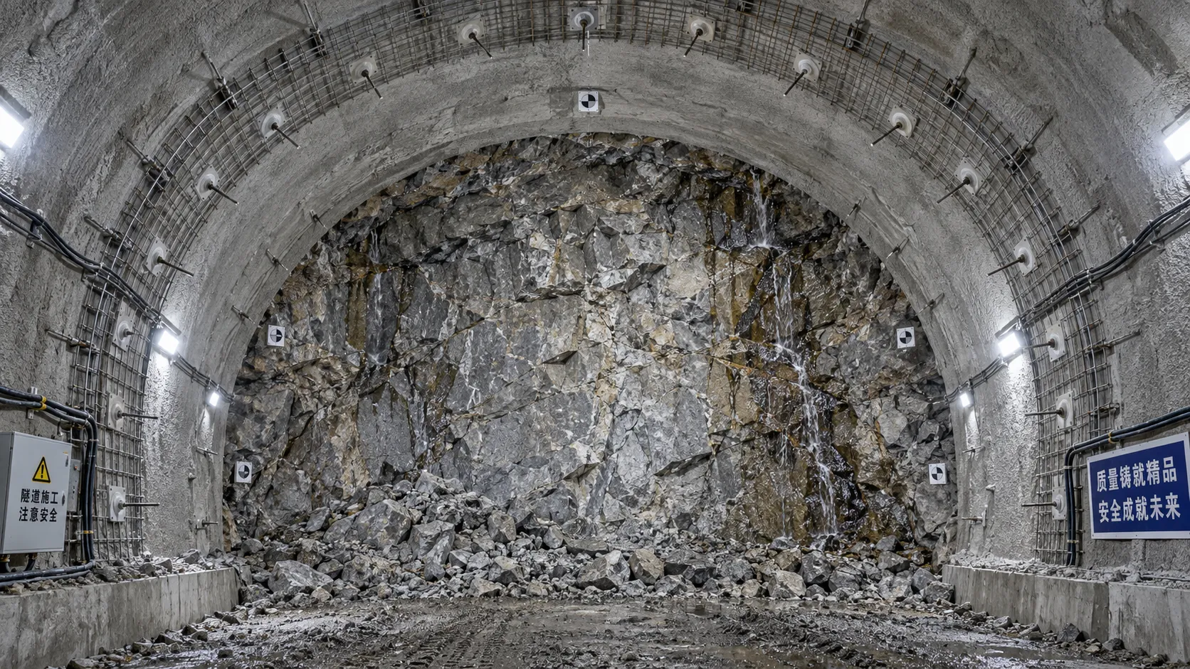
When rock reinforcement in tunnel construction must change after blasting
Rock reinforcement in tunnel construction must change when blasting reveals overbreak, weak joints, water inflow, or deformation. Discover key post-blast support decisions.
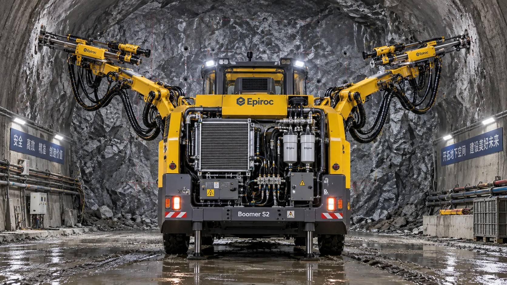
How tunnel hydraulic systems influence drill jumbo uptime underground
Tunnel hydraulic systems directly influence drill jumbo uptime. Explore how stable pressure, clean oil, cooling, and maintainable design reduce underground downtime.
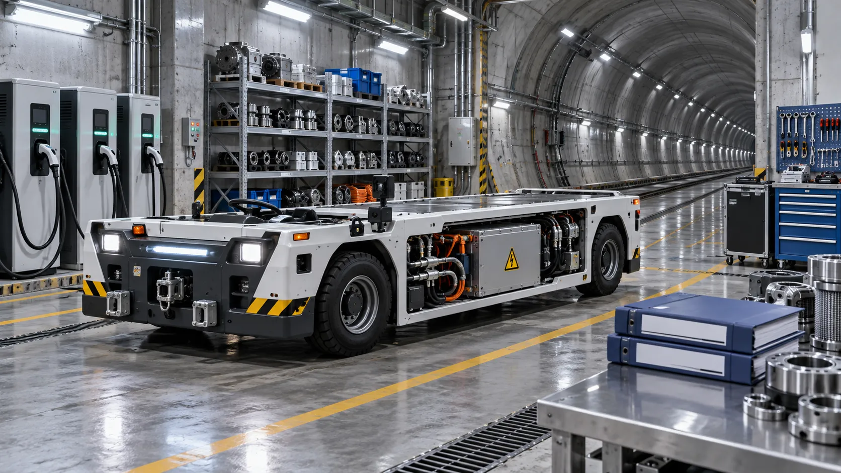
What to verify before appointing a tunneling vehicles manufacturer
Choosing a tunneling vehicles manufacturer? Verify application fit, reliability, compliance, parts support, training, and channel terms before appointing a partner.
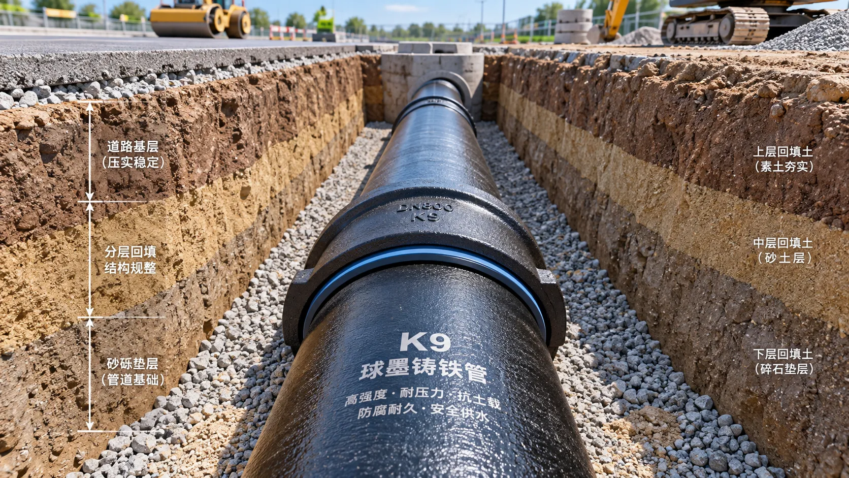
Selecting K9 Ductile Iron Pipe for Buried Water Pipeline Conditions
K9 ductile iron pipe selection for buried water pipelines: compare pressure duty, joints, soil loads, corrosion protection, and installation controls for reliable long-term performance.
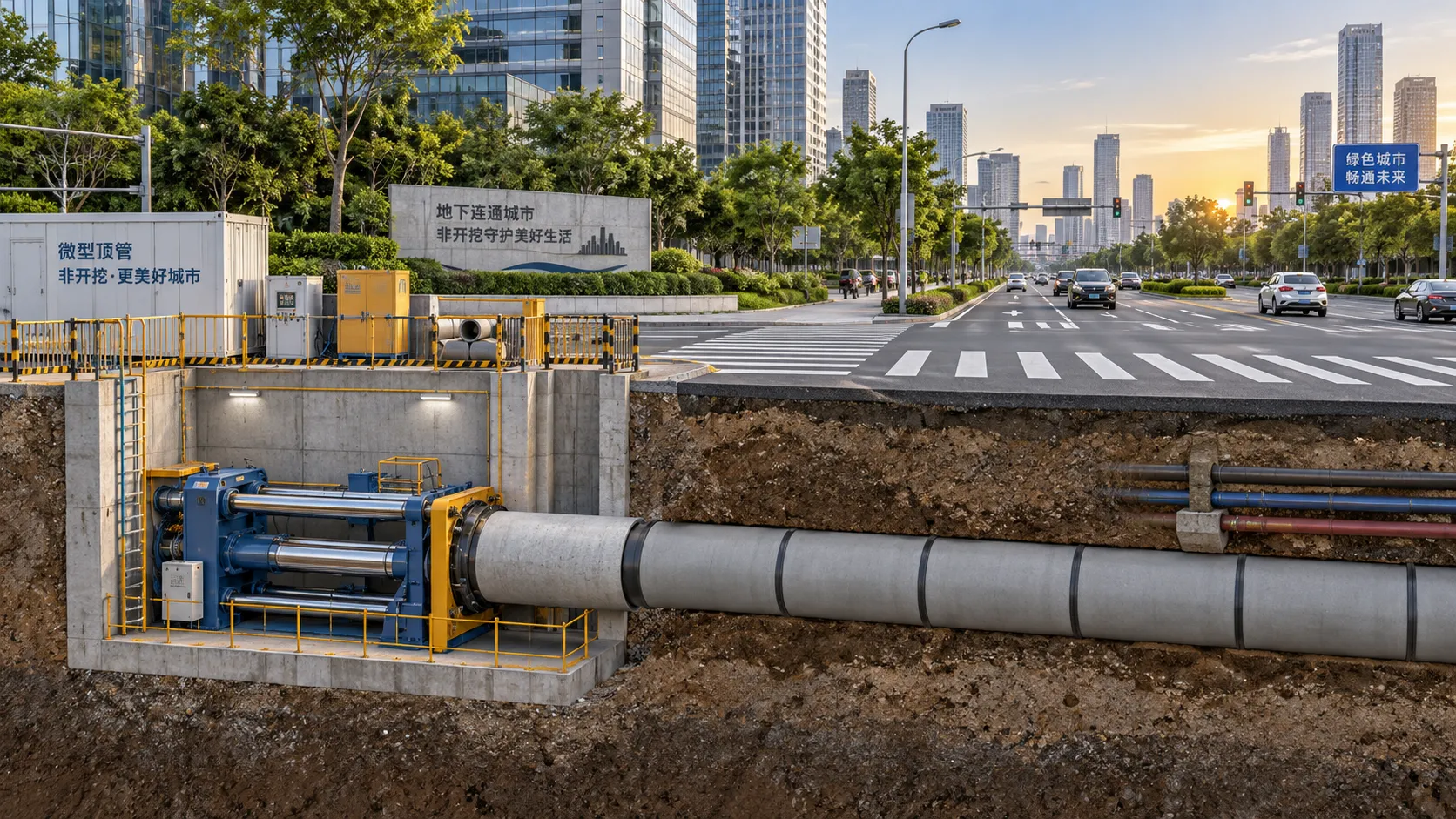
Where Trenchless Technology Delivers the Best Value in Urban Utility Projects
Trenchless Technology applications deliver high value in urban utility projects by reducing disruption, protecting critical crossings, and improving project outcomes.
Related News
- 00
0000-00
Tunnel Boring Machine Costs: Budgeting for Purchase, Operation, and Project Risk - 00
0000-00
Open-Pit Haulage Cost Analysis: How Mine Managers Can Cut Cost per Tonne - 00
0000-00
Tunnel Construction Innovations That Reduce Risk and Schedule Delays on Urban Projects - 00
0000-00
TBM Disc Cutter Design: Key Geometry and Load Factors for Hard Rock Tunnelling - 00
0000-00
Hydraulic Tipping Stability Risks in Multi-Axle Dump Special Trailers
Weekly Insights
Stay ahead with our curated technology reports delivered every Monday.