How to Size Mine Dewatering Equipment for High-Flow Underground Operations





A high-flow underground dewatering system should be sized from the maximum credible hydraulic duty, not from an average water inflow estimate. The selected pumps, pipes, sumps, controls, and electrical supply must continue removing water when groundwater surges, a development heading breaks into a wet zone, suspended solids rise, or one unit is unavailable. A pump that meets the normal flow rate on paper can still fail the operation if its actual operating point falls outside the stable part of its curve after lift and pipe losses are added.
Start by defining the water balance at the location where water is collected. Separate persistent groundwater seepage from intermittent sources such as drilling water, washdown, fractured-zone inflow, process leakage, and water released from temporary storage. These sources do not necessarily peak at the same time. The design case should describe the combination that could occur during an operationally realistic upset, rather than simply adding every theoretical source without examining timing.
Establish the duty point before choosing a pump
The required duty point consists of flow rate and total dynamic head. Flow rate is the volume that must be removed over time; head is the energy needed to move that water from the sump to its discharge point. Both values need a defined basis: normal operation, elevated inflow, and upset or contingency operation. Without those distinct cases, it is easy to select one large pump that runs inefficiently during ordinary conditions and still lacks capacity during a water event.
For staged mine drainage, calculate the duty at each stage. Water may be lifted from a face sump to an intermediate station, then transferred through a borehole or decline line to surface treatment. The pump at the lowest level does not automatically see the entire mine depth as static lift. Its duty depends on the elevation difference to the next receiving point, the pressure in the downstream system, and losses in its own discharge route. Conversely, a common surface header can impose backpressure on several stations at once, altering their operating points.
A practical flow basis should include:
- Base inflow: the sustained quantity expected while the relevant workings are active.
- Peak operational inflow: water entering during normal mine activities, including periods when cleaning or drilling adds solids and water simultaneously.
- Credible upset inflow: a defined short-duration surge or localized breakthrough that the sump and pumping arrangement must manage without flooding critical access or electrical infrastructure.
- Future geometry: additional depth, longer pipe runs, new levels, or a changed discharge location that will alter the head requirement before the equipment reaches the end of its intended service.
Peak flow and peak head are often treated as independent values, yet they interact. As flow rises, friction loss rises sharply. A system can pass its required base volume but lose useful capacity during the very event that calls for higher pumping. For this reason, the pump curve and system curve should be reviewed together at more than one flow condition.
Build total dynamic head from the actual route
Total dynamic head is commonly expressed as static lift plus friction losses and required discharge pressure. Static lift is the vertical elevation difference between the effective sump water level and the destination water level, not simply the depth written on the mine plan. Sump level changes with pump cycling, and the discharge point may be a tank, a settling facility, a pressurized header, or a rising main with a varying water level.
Friction loss requires more than pipe diameter and route length. Include straight pipe, bends, tees, reducers, non-return valves, isolation valves, strainers, flow meters, hose connections, and worn fittings. Flexible hose used for temporary face drainage can impose much higher loss than a comparable rigid pipe, particularly if it is kinked, poorly supported, or fitted with repeated couplings. Abrasive slurry also roughens internal surfaces over time, so a clean-pipe calculation should not be treated as the final condition where long service life is expected.
Pipe diameter is a system decision, not a simple accessory choice. A small rising main reduces initial material and installation work but can force higher pump speed, increase energy consumption, and leave little margin as the line ages. An oversized line lowers friction but may make low-flow operation troublesome, increase installation constraints, and retain settled solids if velocity is inadequate. Select the diameter against the expected operating range, including the minimum flow condition where solids must remain mobile and the maximum condition where losses remain acceptable.
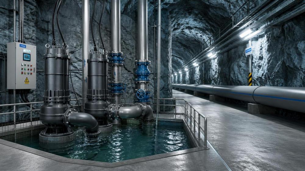
Parallel pump operation deserves a separate curve review. Two identical pumps sharing a header do not each deliver their individual single-pump flow at the same head. The combined flow changes the system friction, while the shared header and check valves create additional losses. A vendor curve for a single pump is insufficient for a station intended to run two or three pumps simultaneously. Ask for a combined operating assessment using the proposed pipework, fittings, and header arrangement.
Match pump hydraulics to water quality and solids behavior
Clear groundwater, silty runoff, drill cuttings, and abrasive fines place very different demands on equipment. A high-head multistage pump may be efficient with relatively clean water but can be unsuitable at a collection point where coarse solids and fibrous debris enter the sump. A solids-tolerant submersible unit can withstand rougher inflow, yet its head capability, cable arrangement, cooling method, and maintenance access must suit the station.
Do not size solely from the largest particle expected to pass. Particle hardness, shape, concentration, and sedimentation behavior affect wear and blockage risk. Angular hard-rock fines wear impellers, volutes, seals, and elbows differently from soft sediment. Long fragments of geotextile, timber, cable ties, or blasting-related debris may foul a passage even when the nominal solids size appears acceptable. Where the pump must be protected, specify the separation method as part of the hydraulic system: a settling bay, trash screen, removable basket, vortex inlet, or upstream sump geometry. A fine screen that blinds frequently is not protection; it becomes the restriction that causes overflow.
Sump design determines whether the pump receives stable water. The useful live volume must absorb the difference between inflow and available pumping rate during starts, stops, or a pump changeover. It also needs enough depth to prevent vortexing and air entrainment at the suction. Excessive turbulence, a short suction run, or an inlet aimed directly at the pump can create fluctuating current and erratic discharge even when the selected pump is hydraulically correct.
Submersible pumps avoid many priming concerns, but their installation still needs attention to cooling, cable protection, retrieval, and sediment build-up. Dry-installed centrifugal pumps require adequate net positive suction head available, a flooded suction or reliable priming method, and a layout that prevents air pockets on the suction side. Recurrent seal failures or noisy cavitation should not be dismissed as a pump defect until the suction conditions, sump level, and inlet geometry have been checked.
Use duty segregation rather than one oversized unit
For high-flow duties, a staged arrangement often provides better control than a single pump sized for the entire forecast peak. Small or medium units can handle normal inflow, with additional pumps starting as sump level rises. This arrangement reduces energy waste at low inflow, permits maintenance without complete loss of pumping, and gives clearer information about changing groundwater conditions from run-time records.
Equipment redundancy should be expressed in terms of remaining duty, not simply the number of installed pumps. If the required peak rate is met only when every pump is available, there is no meaningful capacity reserve. If one unit is out of service, the remaining equipment must either sustain the selected contingency duty or the sump storage must safely bridge the repair period. The appropriate choice depends on how quickly a spare can be deployed, access conditions, the consequences of rising water, and whether a second drainage path exists.
Power, controls, and access are part of capacity
Hydraulic capacity has little value when the electrical system cannot start or run the intended pump combination. Confirm motor starting current, voltage drop along underground cables, transformer capacity, variable-speed drive limits, and the effect of simultaneous starts after a power restoration. A large motor can be technically suitable at the pump station but impractical on a remote distribution network. Soft starting or variable-speed control may reduce starting stress, although the drive enclosure, cooling, harmonic considerations, and fault response need to fit the mine environment.
Backup power must be evaluated through the complete chain: alternate source, transfer arrangement, protected feeder, controls, and the pumps required under the contingency scenario. A standby generator located beyond a flood-prone route or a backup feeder sharing the same vulnerable cable path does not provide independent resilience. Where electrical continuity cannot be guaranteed, sump storage, mobile emergency units, and a gravity bypass may each have a role, but their actual deployment time and connection requirements need to be credible.
Level instrumentation should use more than one point of reference where flooding consequences are severe. A primary continuous level signal can support sequencing and trend analysis, while independent high-level and high-high-level switches provide alarm and emergency start functions. Sensors should be located where foam, sediment, turbulence, and debris will not routinely create false readings. A low-level stop set too aggressively may protect against dry running but leave sediment to consolidate around a submersible pump; setpoints must reflect both equipment protection and sump cleaning practice.
Remote monitoring is most useful when it records conditions that explain performance: sump level, pump status, motor current, discharge pressure, flow where practical, starts, run time, and alarm history. A falling discharge pressure with rising current may indicate a developing blockage or mechanical issue, while falling current and unstable flow can point to air entrainment or loss of suction. Trends are more informative than isolated alarms because groundwater behavior and line condition change gradually before a complete failure occurs.
Procurement data that prevents late redesign
A request for Mine Dewatering Equipment should state the required duty cases, elevation profile, pipe material and nominal internal diameter, total route length, fittings, water chemistry, temperature, expected solids, power supply, installation configuration, control philosophy, and maintenance access. Specify whether performance is required at the pump discharge flange or at the final discharge point. Mixing these reference points produces conflicting quotations and false comparisons.
Request certified pump curves at the proposed speed and impeller diameter, motor data, materials of construction, seal arrangement, allowable solids information, minimum submergence or suction requirements, dimensions, lifting mass, and maintenance clearances. For a multistage or high-head installation, confirm the maximum working pressure of the pump casing, pipe, couplings, valves, gauges, and restraints. The highest pressure may occur near the pump during a transient, not at the discharge point.
Water hammer deserves review where long rising mains, rapid valve closure, or sudden pump trips are present. Check valves that slam, abrupt drive trips, and poorly placed air valves can create pressure excursions beyond the steady-state calculation. The solution may involve valve selection, controlled ramp-down, surge protection, air management, or changes to the line route. Treat it as a system issue early, because retrofitting protection after the pipework is installed is often disruptive underground.
Before final selection, test the proposed configuration against a simple failure narrative: a peak inflow begins while the lead pump is running, one duty pump does not start, and the discharge header sees its highest normal backpressure. If the station still maintains a controlled water level, or has documented storage and response time to do so, the design has a defensible operating basis. If it depends on ideal water quality, clean pipe, full voltage, and every pump being available, the apparent capacity is too fragile for a high-flow underground operation.
Related News
How to Evaluate European Drill-and-Blast Tunnelling Contractors for Complex Projects
Drill and blast tunnelling contractors Europe: learn how to assess geology expertise, blast control, equipment reliability, safety, and programme resilience for complex projects.
Which Trenchless Construction Technique Fits Your Utility Crossing Conditions?
Trenchless construction techniques compared for utility crossings: choose HDD, microtunnelling, pipe jacking, or auger boring based on ground, accuracy, access, and risk.
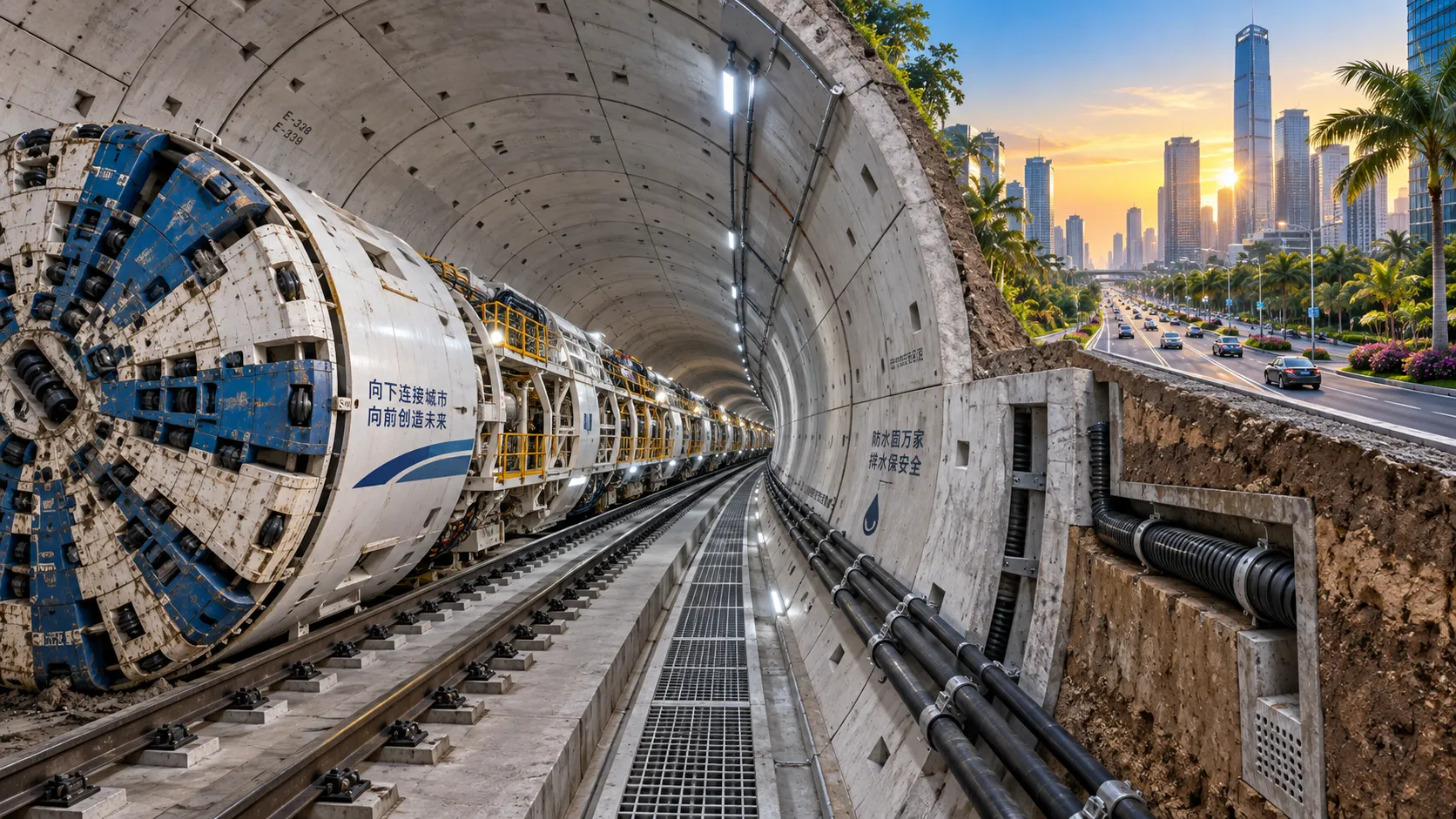
What Is Driving Metro Tunnelling Demand Across Southeast Asia’s Major Cities?
Metro tunnelling Southeast Asia is accelerating as major cities tackle congestion, flooding, and connectivity. Explore the market forces, technical risks, and opportunities shaping demand.
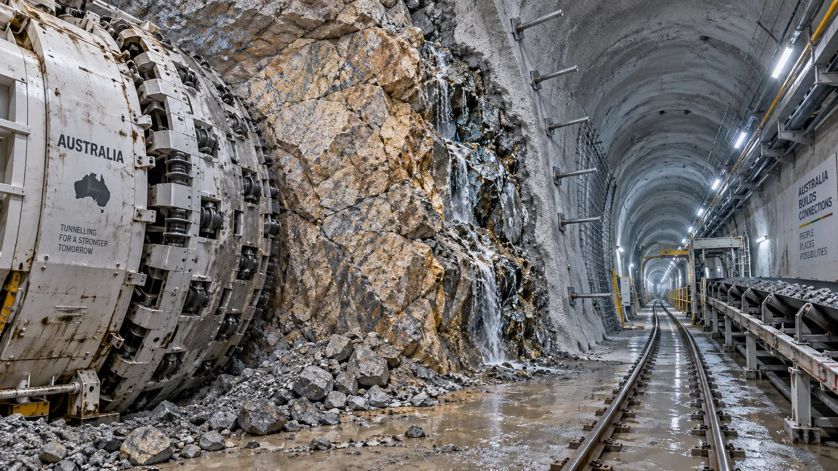
Hard Rock Tunnelling in Australia: Selecting Methods for Variable Ground Conditions
Hard rock tunnelling in Australia: compare TBM, drill-and-blast and hybrid methods to manage variable ground, reduce risk and protect project costs.
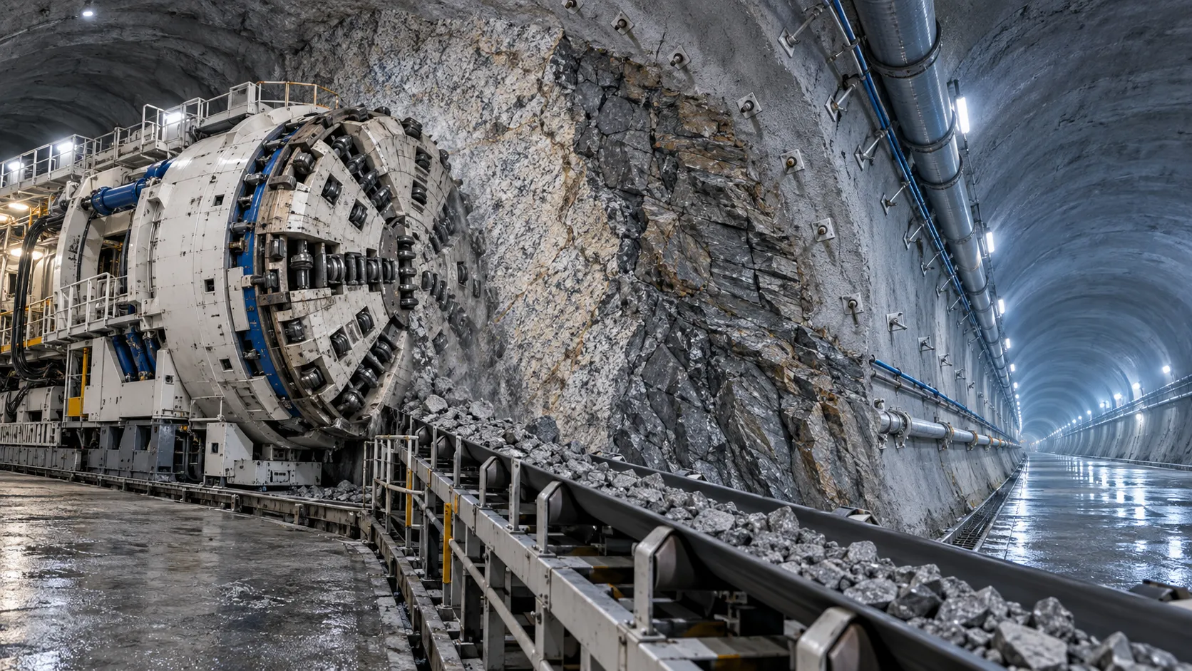
Hydropower Tunnel Excavation: Selecting Methods for Variable Rock Conditions
Hydropower tunnel excavation methods for variable rock conditions: compare TBM, drill-and-blast, and hybrid strategies to improve safety, progress, and project control.
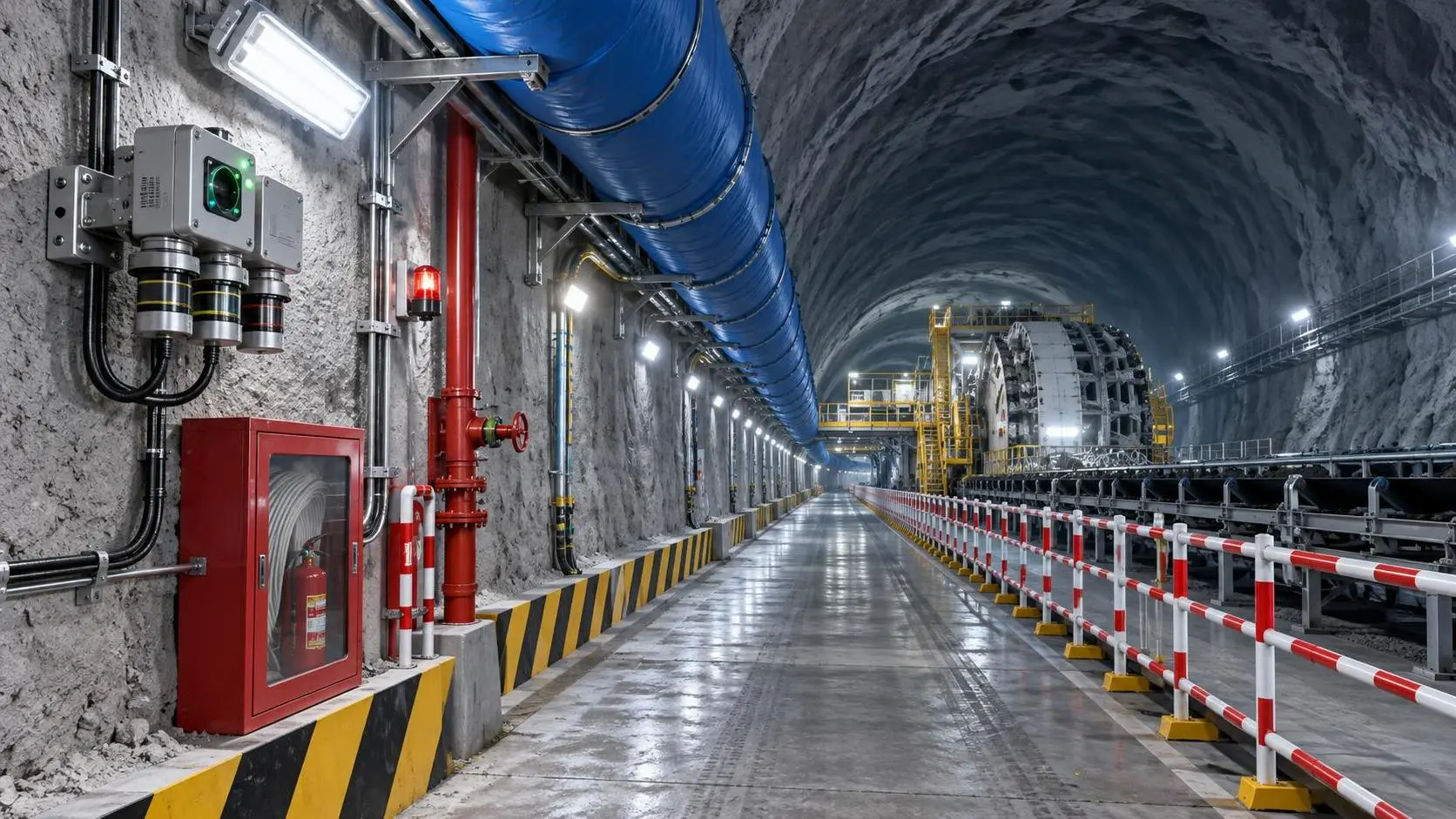
How to Select Underground Safety Equipment for Tunnelling by Hazard and Work Zone
Underground Safety Equipment for tunnelling: match protection to hazards, work zones, compliance, and emergency needs with this practical selection guide.
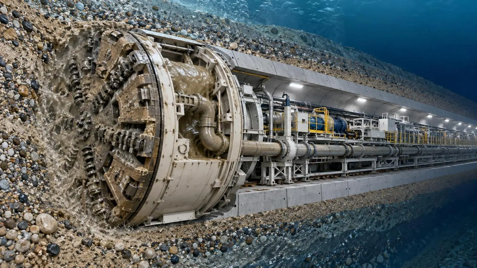
EPB or Slurry Shield? Selecting Soft-Ground Tunnelling Equipment by Soil Conditions
Tunnel Excavation Equipment for soft ground: compare EPB and slurry shields by soil, groundwater, settlement risk, and project logistics to choose confidently.
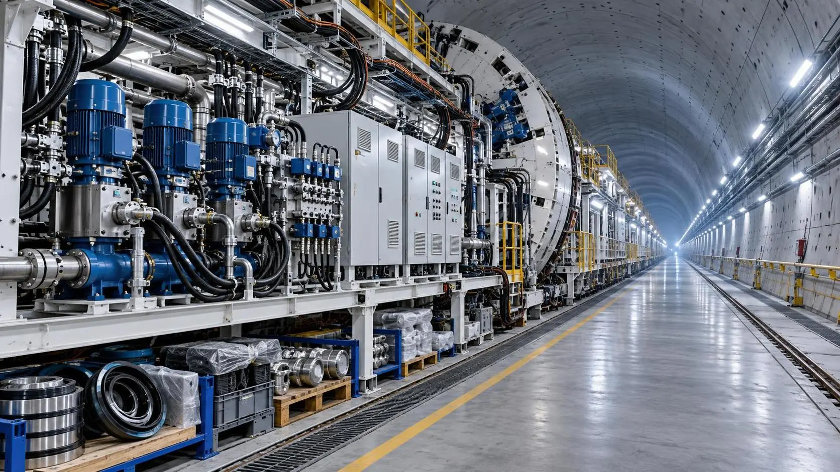
How to Specify TBM Backup System Parts for Reliable Long-Distance Tunnelling
TBM backup system parts: learn how to specify reliable spares for long-distance tunnelling, reduce downtime, ensure compatibility, and speed underground recovery.

How to Size Open Pit Mining Trucks for Haul Distance, Grade, and Payload?
Open Pit Mining Trucks: learn how to match payload, haul distance, grade, road resistance, and loading capacity for safer, lower-cost mine operations.
Related News
- 00
0000-00
How to Evaluate European Drill-and-Blast Tunnelling Contractors for Complex Projects - 00
0000-00
Which Trenchless Construction Technique Fits Your Utility Crossing Conditions? - 00
0000-00
What Is Driving Metro Tunnelling Demand Across Southeast Asia’s Major Cities? - 00
0000-00
Hard Rock Tunnelling in Australia: Selecting Methods for Variable Ground Conditions - 00
0000-00
Hydropower Tunnel Excavation: Selecting Methods for Variable Rock Conditions
Weekly Insights
Stay ahead with our curated technology reports delivered every Monday.