
Matching Cutter Suction Dredger Capacity to Channel Dredging Conditions





Capacity Matching Starts with the Ground, Not the Model Number
Channel dredging programmes often lose time because dredger capacity is discussed as a single output figure. In practice, production depends on a chain of conditions: material strength, particle size, cut depth, water depth, discharge distance, pipeline arrangement, swing pattern, and the destination for the dredged material. A cutter suction dredger that appears suitably sized on a brochure may be underpowered for consolidated soil, or unnecessarily large when the work is limited by discharge placement rather than excavation.
For project managers, the objective is not to select the largest available dredger. It is to select a dredging system that can maintain stable, verifiable production across the expected range of channel conditions while keeping fuel use, wear, mobilization complexity, and downtime within the project plan.
A practical assessment begins by separating three questions that are often combined too early:
- Can the cutterhead excavate the in-situ material at the required depth and profile?
- Can the pump and pipeline transport the resulting slurry to the discharge point without frequent blockage or excessive wear?
- Can the dredger complete the required volume within the available working window after allowing for positioning, maintenance, weather, survey checks, and support operations?
Only when these questions are tested together does nominal dredger capacity become useful for procurement or deployment planning.
Define the Channel Condition Before Comparing Dredger Outputs
Channel projects rarely involve one uniform soil type. A reach may contain soft silt near the surface, sand lenses along the side slopes, compacted material around bends, and debris or riprap near structures. The relevant investigation is not simply a statement that the material is “sand” or “mud.” It should identify layer thickness, grain-size distribution, density or consistency, possible obstructions, groundwater conditions, and the expected depth of cut.
For granular soils, particle-size data helps predict both excavation behavior and pipeline wear. Fine sand can usually be transported efficiently when the slurry concentration and pipeline velocity are controlled. Coarser sand and gravel may require more cutter torque, greater pump head, more abrasion-resistant components, and closer attention to minimum transport velocity. Cohesive material can create a different problem: it may break off in lumps, restrict cutterhead penetration, or form an inconsistent slurry even when the installed pump power appears sufficient.
Project documents should distinguish between in-situ volume, loose volume, and transported slurry volume. These are not interchangeable. A production estimate based only on the hopper or pump flow rate can overstate the actual quantity removed from the channel because water entrainment, soil bulking, and operational interruptions affect delivered solids volume.
Grain-size testing should follow a method appropriate to the material range being evaluated. ASTM D6913/D6913M provides a standard test method for particle-size distribution of soils using sieve analysis, while fine fractions may require additional testing methods. The results do not select a dredger by themselves, but they give the engineering team a more defensible basis for assessing cutter wear, pump suitability, and pipeline risk. Source: ASTM D6913/D6913M, Standard Test Methods for Particle-Size Distribution (Gradation) of Soils Using Sieve Analysis.
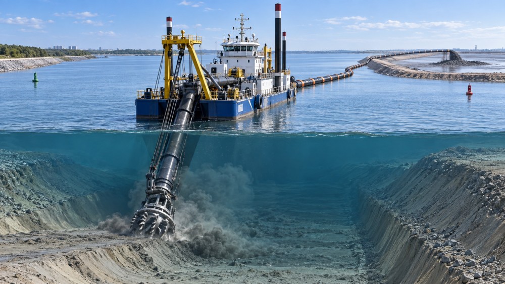
Excavation Capacity and Hydraulic Transport Capacity Must Be Balanced
A cutter suction dredger operates as both an excavator and a hydraulic transport system. The cutterhead loosens material, while the dredge pump draws the slurry through the suction line and sends it through a floating, submerged, or shore pipeline. If cutter production is greater than the hydraulic system can transport, material can accumulate around the cutterhead or settle in the pipeline. If pump capacity is high but the cutter cannot release material fast enough, installed power is not converted into useful output.
This balance is especially important where the design calls for a long discharge line. Every pipeline section adds friction loss. Bends, reducers, flexible connections, floating hoses, elevation changes, and worn pipe interiors can further change the operating point. A dredger that performs acceptably with a short pipeline to a nearby disposal area may not sustain the same solids production when the discharge line is extended across a tidal flat or over a containment bund.
Procurement teams should request a pump and pipeline calculation based on the intended discharge arrangement rather than a generic pumping distance. The calculation should state the assumed pipe diameter, line length, elevation profile, slurry density, expected solids characteristics, booster-pump arrangement if any, and design operating range. Where the contractor expects the discharge route to change during the work, the assessment should also identify the point at which an additional booster becomes necessary.
The relevant output is therefore not merely water flow. It is the expected solids production at the cutter, under the defined material and pipeline conditions, with enough margin to manage reasonable variation in the work area.
Why Cutter Power Alone Can Mislead
Higher cutter power may be necessary when compacted sand, stiff clay, weathered material, or embedded debris is expected. Yet a powerful cutter does not remove the need to match suction flow and pump head. Aggressive cutting can generate oversized clods or uneven feed, which may reduce hydraulic transport stability. Conversely, a smaller cutterhead may make controlled progress in soft sediments but become the limiting factor when the channel includes denser layers.
Managers should ask suppliers and contractors to explain how cutterhead diameter, installed cutter power, rotational speed range, tooth or blade arrangement, and swing winch capacity are matched to the soil description. The question is not whether a component is “heavy duty,” but whether it has been selected for the anticipated cutting resistance and required production pattern.
Water Depth, Cut Geometry, and Positioning Affect Real Production
Channel depth is more than an access condition. It affects ladder angle, suction geometry, cutterhead reach, spud loading, and the number of passes needed to achieve the design section. A dredger that can reach the required depth in theory may work inefficiently if the ladder angle leaves poor control at the bottom of the cut or if the side-slope profile requires repeated trimming passes.
In narrow channels, swing width can become the constraint. The dredger may need to make shorter, more frequent sweeps, reposition spuds often, or work around navigation restrictions. A broad basin may allow a wider swing and a more regular cut pattern, while a confined channel beside quay walls, bridges, pipelines, or revetments requires more conservative positioning and closer survey control.
Before final selection, the project team should compare the dredger’s working envelope with the channel cross-section and obstructions. This review should include:
- maximum and minimum water depth during the work period;
- required dredging depth and allowable overdepth;
- channel width, side slopes, bends, and turning areas;
- clearance from structures, utilities, navigation lanes, and environmentally sensitive boundaries;
- spud arrangement, anchoring needs, and the availability of support vessels;
- tidal range, current direction, wave exposure, and seasonal access limitations.
These factors determine how much of a shift can be spent cutting productively. A production target based on uninterrupted pumping is rarely suitable for a constrained channel where repositioning, survey hold points, and vessel movements are frequent.
Using a Mid-Range Cutter Suction Dredger as a Procurement Reference
For medium-scale channel maintenance or improvement work, a model designation can provide a starting point for technical comparison, but it should not substitute for a project-specific duty point. Where a procurement package is considering a YLCSD300 cutter suction dredger, the useful questions are whether its proposed pump curve, cutter configuration, dredging depth range, discharge arrangement, and installed power match the defined channel section and material investigation.
Model designations often reflect a manufacturer’s product series, while the delivered arrangement may vary with engine selection, pump size, ladder length, electrical systems, discharge pipeline, spud system, and optional booster equipment. A manager should therefore evaluate the submitted technical schedule rather than assuming that two dredgers with similar names will have identical operating capability.
A sound comparison table should separate guaranteed values from indicative values. Guaranteed items may include installed power, pump performance at stated conditions, dredging depth range, pipe diameter, and delivery scope. Indicative production figures should identify the assumed soil, slurry concentration, pipeline length, and operating hours. Without those assumptions, a quoted cubic-metre figure has limited planning value.
Build the Production Estimate Around Working Time
Planning should convert theoretical output into an achievable shift rate. The calculation needs allowances for warm-up, positioning, discharge-line moves, cutter and pump inspections, fuel logistics, survey checks, weather interruptions, and removal of unexpected debris. The exact allowance depends on the project, but excluding these activities creates a schedule that is difficult to defend once operations begin.
A useful approach is to prepare at least three operating cases:
- Base case: expected soil and pipeline configuration under normal access conditions.
- Constrained case: lower production caused by tougher material, longer discharge distance, restricted swing, or additional survey control.
- Recovery case: a practical plan for adding working hours, improving pipeline layout, deploying a booster, or changing the cut sequence if production falls below target.
This approach is more valuable than presenting one optimistic output number. It helps project leaders understand whether schedule resilience comes from dredger capacity, additional support equipment, a larger work window, or a revised disposal strategy.
Quality Control Is Part of Capacity Matching
A dredger can move a substantial amount of material and still fail the channel requirement if the final bed level, side slopes, or clearance zones do not meet the design. Hydrographic surveys should be coordinated with the dredging sequence, particularly where overdepth is limited or where the channel serves vessels with strict draft requirements. The survey specification should define line spacing, sounding density, vertical datum, tolerances, and the treatment of isolated high spots.
Mechanical condition also changes actual capacity over time. Cutter teeth, liners, impellers, pump casings, pipeline sections, bearings, seals, and winch components should be included in the inspection plan. Abrasive material can gradually reduce pump performance, while damaged pipeline joints may cause leaks or air entry that destabilizes slurry transport. Spare parts should be assessed against expected wear exposure and delivery lead time, not added as a generic checklist item.
For dredging management and material-placement planning, the U.S. Army Corps of Engineers notes the importance of considering dredging method, material characteristics, transport, placement, and environmental controls as connected elements of a dredging operation. That systems approach is relevant even where local rules and contract conditions differ. Source: U.S. Army Corps of Engineers, EM 1110-2-5025, Dredging and Dredged Material Management, 2015.
Safety, Environmental Controls, and Mobilization Constraints
Capacity decisions can create avoidable operational risk if they focus only on production. A larger or more powerful dredger may require heavier lifting arrangements, more complex mobilization, wider exclusion areas, greater fuel handling capacity, or additional electrical and mechanical support. The dredging plan should address personnel transfer, anchor or spud movements, rotating equipment guarding, confined-space procedures where applicable, emergency communications, and interaction with passing vessels.
Environmental controls are equally site-specific. Turbidity, sediment release, noise, disposal-area containment, contaminated-material handling, and restrictions around sensitive habitats may all affect cut rate, work hours, or discharge routing. The applicable permits and local authority requirements should be confirmed before the production programme is fixed. Where environmental monitoring is required, the monitoring process should be integrated into shift planning rather than treated as an external delay.
Project managers should also inspect the practical mobilization route. Dimensions, transport weight, launch access, assembly area, lifting equipment, floating pipeline storage, and availability of sheltered mooring can determine whether a suitable dredger can be deployed on the planned date. A technically appropriate dredger that cannot be mobilized efficiently may create a larger schedule problem than a smaller unit with a simpler logistics plan.
A Defensible Selection Decision
The right cutter suction dredger is the one that maintains controlled excavation and slurry transport within the channel’s actual physical limits. Selection should be based on investigated material, depth and geometry, discharge duty, working-time assumptions, maintenance exposure, and acceptance requirements. A model review is useful only when it is tied to those conditions.
For a project manager, the strongest procurement file is one that records the assumed duty point, identifies the conditions that could reduce output, and defines how performance will be verified during the work. That provides a clearer basis for comparing equipment proposals and a more realistic path to completing the channel to the required profile.
Related News
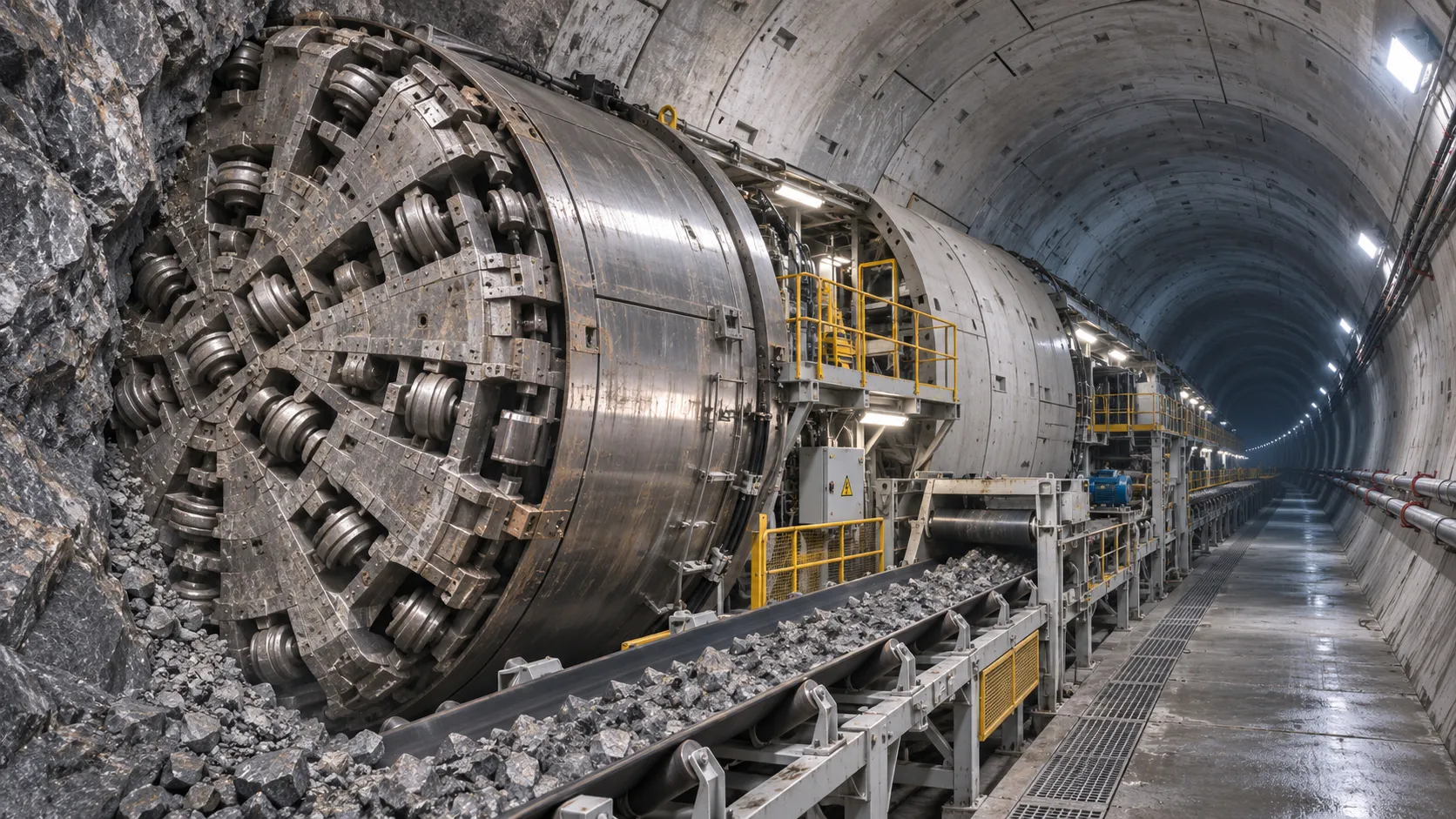
How TBM Excavation Works in Rock and Soft Ground: A Practical Guide
TBM Excavation in rock and soft ground explained: compare machine types, ground support, spoil removal, and the factors that guide smarter project planning.
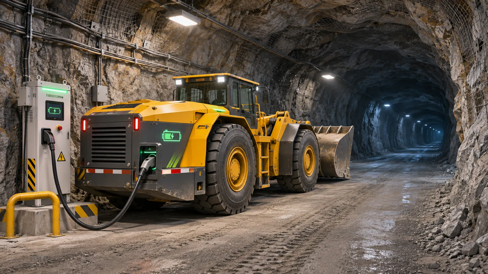
Choosing a Zero-Emission Underground Equipment Supplier: What to Check
Choosing a zero emission underground equipment supplier? Compare duty-cycle performance, charging, safety, total costs and support before you commit.
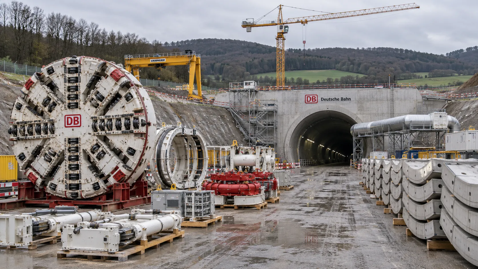
Construction Starts on Germany's Pfaffensteig Rail Tunnel, With Two TBMs Planned
Pfaffensteig rail tunnel construction is underway in Germany. Discover how two planned TBMs will support the 11-kilometre project near Stuttgart.
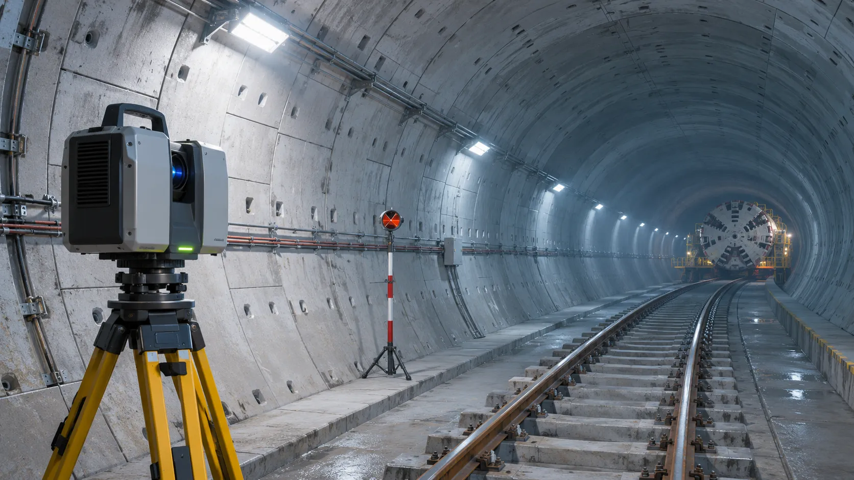
How Real-Time Underground Mapping Systems Work in Tunneling
Discover how real-time underground mapping systems guide tunneling teams, integrate sensor data, and support confident decisions with verified accuracy.
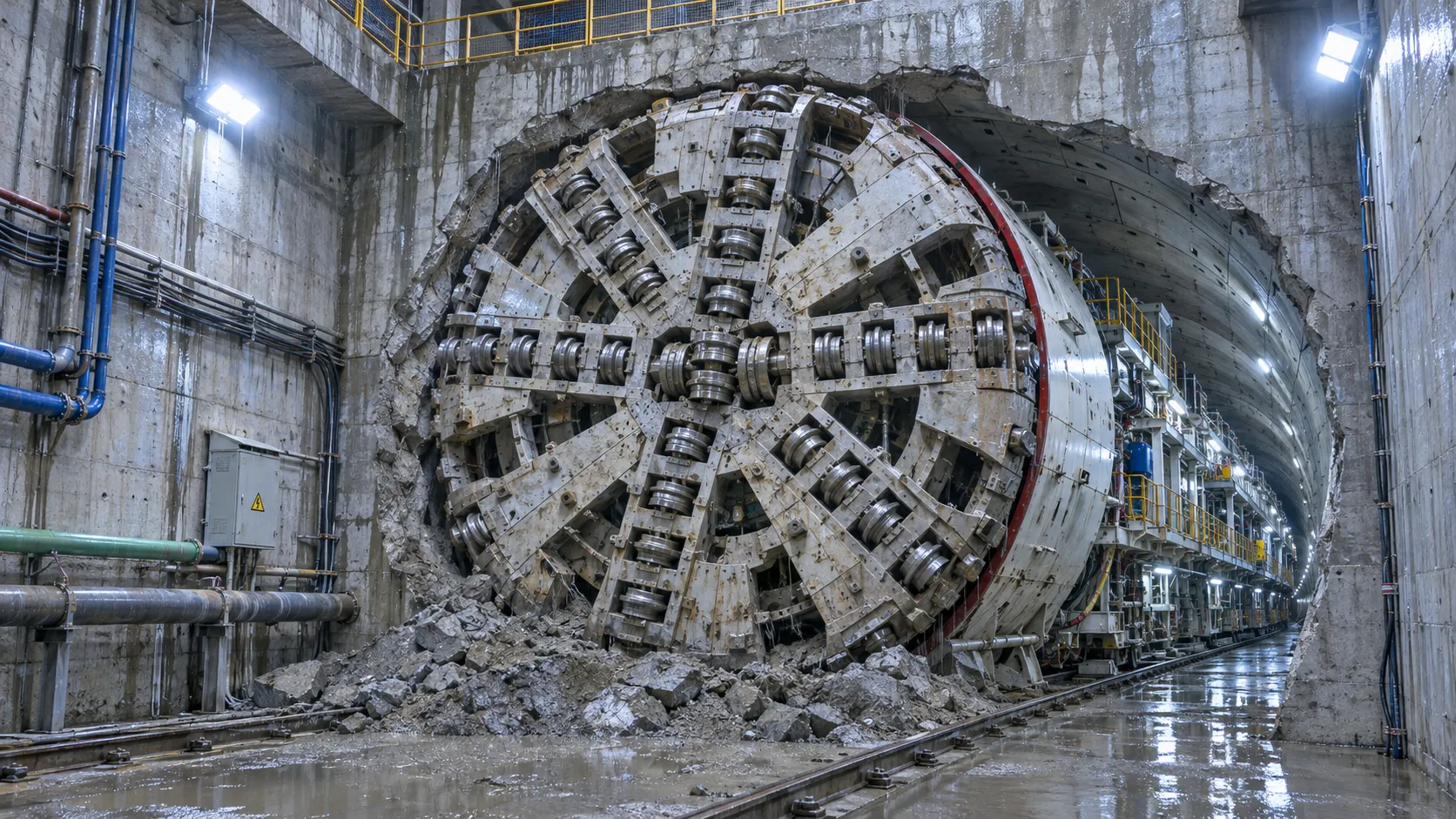
First Mechanized Tunnel Crossing Beneath the Panama Canal Completed
Panama Canal tunnel crossing: Explore the reported Metro Line 3 milestone and what it could mean for future underwater tunneling projects.
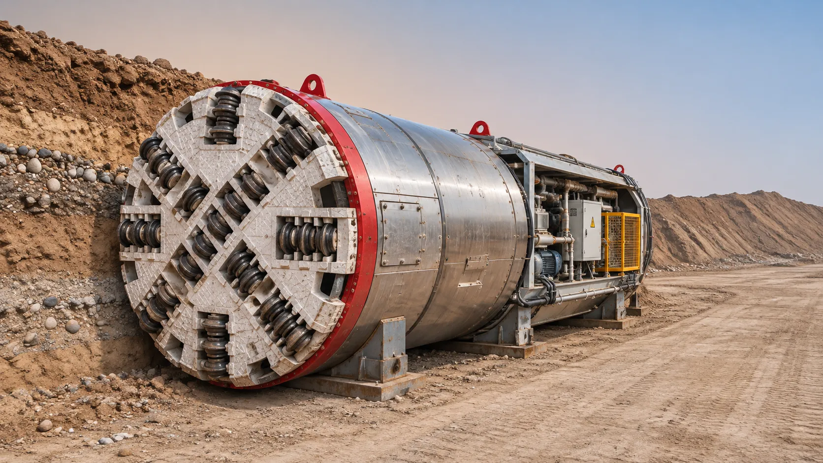
Underground Utility Construction Equipment: Choosing by Ground Conditions
Choose underground utility construction equipment with confidence. Compare trenching, HDD, microtunnelling and TBMs by ground conditions, risk and cost.
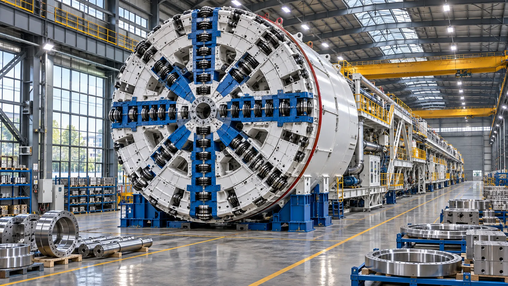
China Sets Tunnel Boring Machine Export Controls as India Pushes Local Production
China tunnel boring machine export controls could reshape procurement as India pushes local production. Explore potential supply and project impacts.
Choosing a Trenchless Pipeline Installation Contractor: Key Qualifications
Choose a trenchless pipeline installation contractor with confidence. Learn how to assess experience, equipment, safety, costs, and project risks before you hire.
China's 70% TBM Share and Export Controls Challenge India's Local Production
China's TBM export controls could challenge India's local production and infrastructure sourcing. Explore the potential risks and procurement options.
Related News
- 00
0000-00
How TBM Excavation Works in Rock and Soft Ground: A Practical Guide - 00
0000-00
Choosing a Zero-Emission Underground Equipment Supplier: What to Check - 00
0000-00
Construction Starts on Germany's Pfaffensteig Rail Tunnel, With Two TBMs Planned - 00
0000-00
How Real-Time Underground Mapping Systems Work in Tunneling - 00
0000-00
First Mechanized Tunnel Crossing Beneath the Panama Canal Completed
Weekly Insights
Stay ahead with our curated technology reports delivered every Monday.