
Mine Drainage Equipment Selection: Flow Rate, Head, and Solids Handling





Mine Drainage Equipment Selection: Flow Rate, Head, and Solids Handling
Selecting mine drainage equipment requires more than matching a pump to a nominal duty point. Underground inflows change, discharge routes lengthen, and water that looks relatively clean can carry enough abrasive fines to shorten component life. A pump may meet its rated capacity on a test stand yet struggle once connected to the actual mine pipework.
The useful question is not simply “What size pump do we need?” It is “Which pumping arrangement will control water across the expected operating conditions, and remain serviceable when those conditions deteriorate?” Answering that means assessing flow rate, total dynamic head, and solids together, then checking power supply, controls, and maintenance access.
Define the water problem before choosing the pump
Separate temporary face dewatering from permanent mine drainage. A pump following a drilling jumbo or advancing tunnel face needs mobility, manageable connections, and tolerance for dirty water. A fixed station transferring collected water up a shaft has a different priority: sustained operation against substantial head, with dependable standby capacity and maintainable infrastructure.
These duties do not necessarily belong on the same pump specification. Where coarse debris enters local sumps, collecting and settling that material before transfer can make a high-head pumping stage more practical. However, settling arrangements require space, cleaning access, and sufficient retention time. A sump that nobody can safely clean eventually becomes a source of concentrated solids rather than protection against them.
UTMD’s coverage of tunnelling, underground transport, and mine automation places drainage within the wider operating system. Water control affects drilling access, LHD travel routes, electrical infrastructure, and equipment availability. A drainage design should therefore be reviewed against the excavation sequence and mine layout, not treated as an isolated equipment purchase.
Flow rate: use an operating range, not one reassuring number
Start with an inflow record that distinguishes groundwater seepage, process water, washdown, and intermittent events. Where measurements are incomplete, identify the uncertainty explicitly. An average taken during a quiet production period is not a reliable basis for handling a new water-bearing zone or an extended shutdown followed by sump recovery.
The selection needs to address three conditions: normal inflow, the credible peak inflow defined by the project assessment, and the capacity needed to lower accumulated water within an acceptable recovery period. Recovery duty includes continuing inflow while the stored volume is being removed. Ignoring that continuing inflow makes drawdown calculations look better than they are.
Usable sump volume matters as much as pump capacity. It is the volume between operating levels, not the entire excavated sump. Sediment accumulation reduces that buffer, while start-stop settings determine cycling frequency. Frequent starts can stress motors and switching equipment; excessively wide level bands may allow water to threaten working areas.
Oversizing is not a harmless precaution. An oversized centrifugal pump can operate away from its preferred range, draw down the sump too quickly, or require throttling that wastes energy. Parallel smaller units may offer better staging and maintenance flexibility, but their combined output must be calculated against the system curve. Two pumps connected to a common rising main do not automatically deliver twice the single-pump flow.
Standby provision should be tested against a failure condition: what drainage capacity remains when one unit, feeder, or discharge route is unavailable? A spare pump on the surface is useful stock, but it is not equivalent to an installed unit that can start before the sump reaches a critical level.
Head: calculate the complete discharge route
Total dynamic head includes the static elevation difference, pipe friction, losses through fittings and valves, and any pressure required at the discharge destination. Where suction and discharge velocities differ materially, the velocity-head difference also belongs in the calculation. Mine depth alone is not the pump duty.
Use the actual pipe internal diameter and route. Long horizontal runs, partially closed valves, check valves, hose couplings, and smaller temporary sections can materially change the result. Assess both initial and foreseeable operating conditions, including route extensions and changes in receiving-water level.
Plot those conditions as system curves against the proposed pump curves. The intersection determines the operating point. Maximum flow and shutoff head are separate endpoints on a centrifugal pump curve; they are not a simultaneous operating capability. A catalogue claiming a high value for each still says little about performance at the required duty.
For approximately turbulent clean-water flow in unchanged pipework, friction head rises roughly with the square of flow. That relationship explains why increasing capacity through an existing small main can demand disproportionately more head and power. Slurry behaviour may differ, so solids-bearing service needs an appropriate hydraulic assessment rather than an unqualified clean-water calculation.
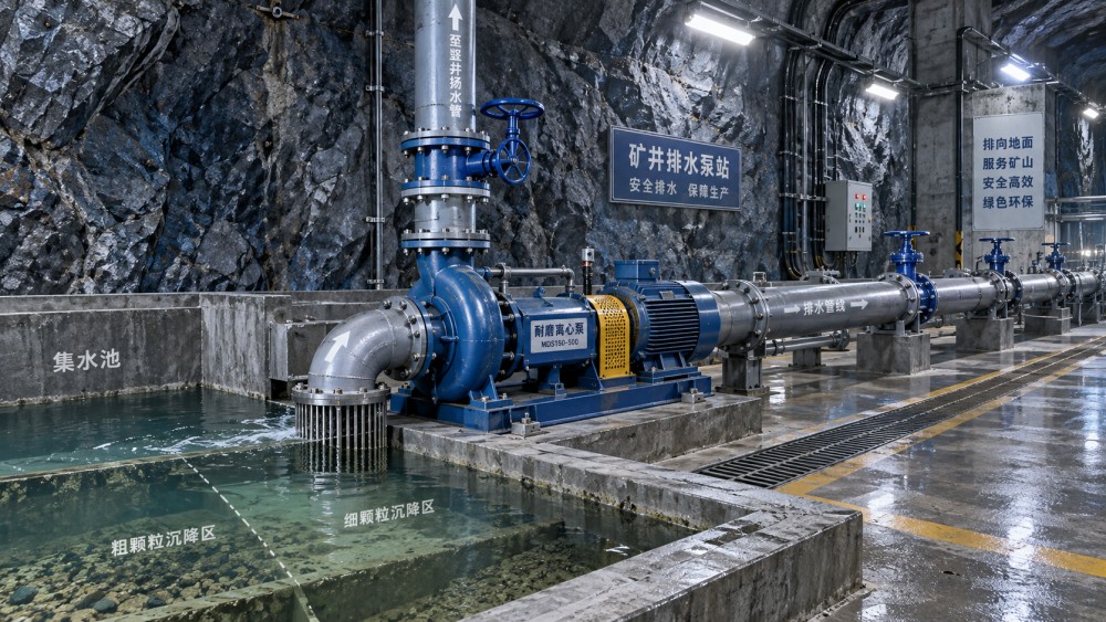
Request curves showing efficiency, absorbed power, and required net positive suction head across the relevant range. Check proximity to the best efficiency point and the manufacturer’s preferred or allowable operating region. For surface-mounted pumps, verify available suction head at the lowest water level and highest relevant temperature. For submersibles, confirm minimum submergence, cooling requirements, and measures against air entrainment.
Deep installations may justify staged pumping, but intermediate stations add controls, storage requirements, and failure interfaces. Direct pumping reduces those interfaces while increasing pressure demands on the pump and pipeline. Evaluate both arrangements with pipe pressure ratings, shutoff conditions, and hydraulic transients in view.
Solids handling: passing a particle is not surviving the slurry
A stated solids-passage size addresses clearance. It does not establish wear life. Fine, hard mineral particles can pass through an impeller without blockage while steadily eroding hydraulic surfaces. Conversely, an occasional large fragment or piece of debris can obstruct a pump handling otherwise low-solids water.
Characterize particle-size distribution, likely maximum particle size, concentration, density, hardness, and shape. State whether concentration is measured by mass or volume. Include water chemistry and temperature: acidic or saline mine water can introduce corrosion mechanisms that a wear-resistant material alone may not address.
Sampling location and timing deserve attention. Water near the sump surface may not represent what enters a bottom-mounted pump after sediment is disturbed. Review conditions during cleaning, restart, and heavy inflow—not just a convenient sample from normal operation.
Vortex or recessed-impeller designs can be useful where debris passage is important, though hydraulic efficiency may be lower than suitable alternatives. Slurry-duty centrifugal pumps are intended for abrasive service, with specific wet-end geometry and wear materials. Multistage pumps can suit high-head duties with sufficiently clean water, but restrictive internal passages and wear-sensitive clearances require caution in dirty service. Selection depends on the actual material, not the equipment label.
Ask suppliers to explain material choices for the measured chemistry and solids. High-chromium alloys, elastomers, and other lining systems have different strengths and limitations. Sharp particles, temperature, chemical exposure, and impact loading can change which choice is sensible.
The discharge line also needs a solids strategy. Velocity must be assessed for deposition risk without creating unnecessary abrasion and energy loss. Low-speed operation through a variable-frequency drive may control sump level well yet allow solids to settle. Shutdown flushing, cleanout access, and restart procedures should be considered where deposits are credible.
Power and maintenance can overturn a good hydraulic choice
Motor sizing should cover absorbed power throughout the intended operating envelope, with appropriate allowance for liquid density, slurry corrections, and drive losses. Do not check only the nominal duty point. Depending on pump geometry, a lower-than-expected system resistance can shift operation toward higher flow and motor overload.
Underground installations also need checks for cable voltage drop, starting conditions, protection settings, and the available supply. Hazardous-area suitability, where applicable, must be established against the mine’s classification and local requirements. Neither a general industrial motor nor an electric drive is automatically suitable for every underground environment.
Variable-speed control can improve operation under changing demand, but it cannot remove the static-head requirement. Confirm the minimum useful speed and permitted operating range. Where solids transport sets a minimum flow, staged pump operation may be preferable to continually slowing one large unit.
Maintenance access is a selection criterion, not a later installation detail. Check whether the pump can be lifted, isolated, drained, and dismantled within the available roadway or chamber. A replaceable wear component offers little practical benefit if removing it requires interrupting a haulage route for an extended period. Confirm spare-part availability and realistic underground replacement procedures.
Compare offers on a common duty envelope
A useful technical enquiry gives every supplier the same operating cases, water characteristics, pipeline assumptions, and installation constraints. Require deviations to be visible. Otherwise, one offer may assume clean water and a new pipeline while another accounts for abrasive solids and the actual discharge route.
- Request predicted duty points for normal operation, peak inflow, recovery, and standby operation.
- Identify whether submitted curves apply to water or include stated slurry-performance corrections.
- Confirm minimum continuous flow, submergence or suction limits, and motor loading across the proposed range.
- Agree commissioning checks for measured flow, pressure, current, level-control operation, and standby changeover.
- Document how alarms, loss of communications, and power interruptions affect drainage availability.
Connected monitoring fits the smart-mine systems UTMD follows, but local protection should not depend solely on network availability. Trending level, flow, discharge pressure, and current together can help identify deteriorating performance. A high sump level alone cannot distinguish increased inflow from a blocked line, worn pump, or failed unit.
Before approving mine drainage equipment, resolve the assumptions most likely to change the choice: uncertain peak inflow, underestimated pipe losses, poorly characterized solids, and inaccessible maintenance arrangements. If those remain open, a precise-looking duty point is not yet a defensible selection.
Related News
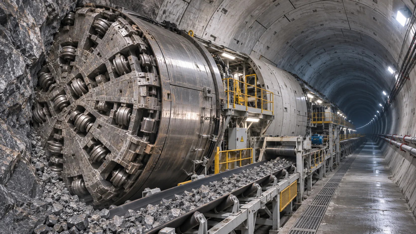
How TBM Excavation Works in Rock and Soft Ground: A Practical Guide
TBM Excavation in rock and soft ground explained: compare machine types, ground support, spoil removal, and the factors that guide smarter project planning.
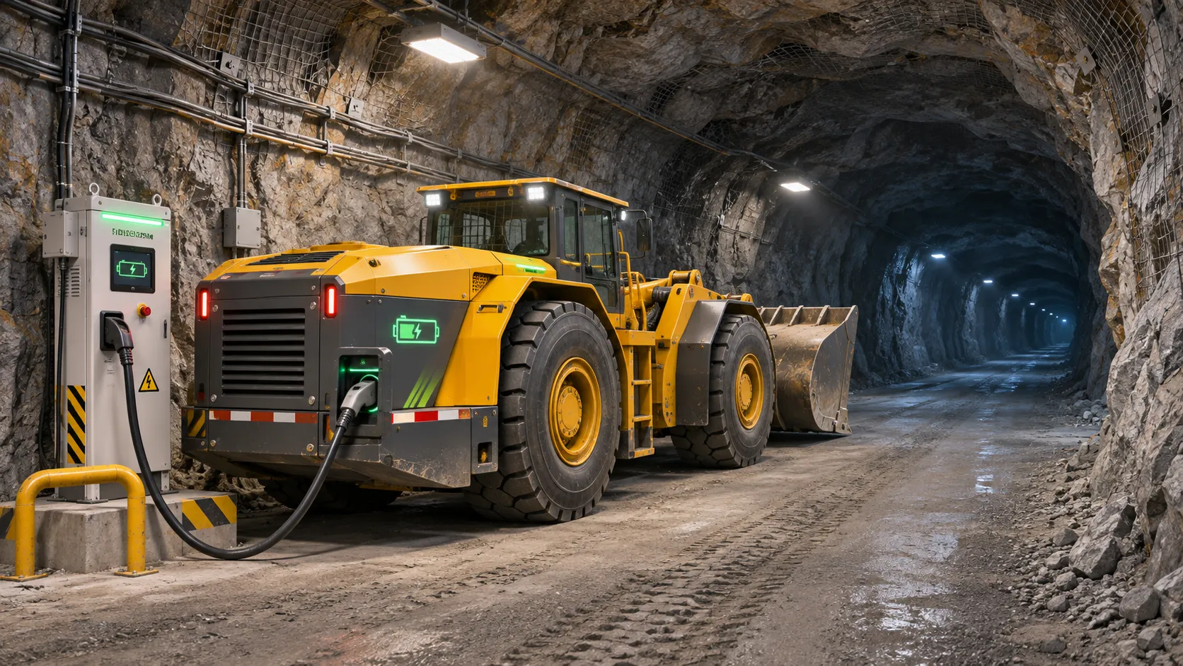
Choosing a Zero-Emission Underground Equipment Supplier: What to Check
Choosing a zero emission underground equipment supplier? Compare duty-cycle performance, charging, safety, total costs and support before you commit.
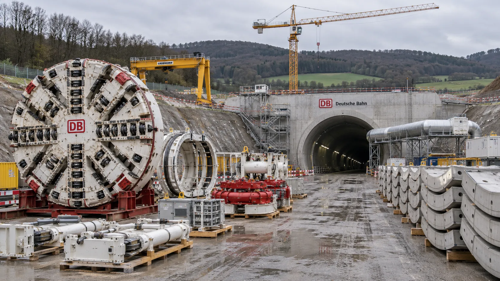
Construction Starts on Germany's Pfaffensteig Rail Tunnel, With Two TBMs Planned
Pfaffensteig rail tunnel construction is underway in Germany. Discover how two planned TBMs will support the 11-kilometre project near Stuttgart.
How Real-Time Underground Mapping Systems Work in Tunneling
Discover how real-time underground mapping systems guide tunneling teams, integrate sensor data, and support confident decisions with verified accuracy.
First Mechanized Tunnel Crossing Beneath the Panama Canal Completed
Panama Canal tunnel crossing: Explore the reported Metro Line 3 milestone and what it could mean for future underwater tunneling projects.
Underground Utility Construction Equipment: Choosing by Ground Conditions
Choose underground utility construction equipment with confidence. Compare trenching, HDD, microtunnelling and TBMs by ground conditions, risk and cost.
China Sets Tunnel Boring Machine Export Controls as India Pushes Local Production
China tunnel boring machine export controls could reshape procurement as India pushes local production. Explore potential supply and project impacts.
Choosing a Trenchless Pipeline Installation Contractor: Key Qualifications
Choose a trenchless pipeline installation contractor with confidence. Learn how to assess experience, equipment, safety, costs, and project risks before you hire.
China's 70% TBM Share and Export Controls Challenge India's Local Production
China's TBM export controls could challenge India's local production and infrastructure sourcing. Explore the potential risks and procurement options.
Related News
- 00
0000-00
How TBM Excavation Works in Rock and Soft Ground: A Practical Guide - 00
0000-00
Choosing a Zero-Emission Underground Equipment Supplier: What to Check - 00
0000-00
Construction Starts on Germany's Pfaffensteig Rail Tunnel, With Two TBMs Planned - 00
0000-00
How Real-Time Underground Mapping Systems Work in Tunneling - 00
0000-00
First Mechanized Tunnel Crossing Beneath the Panama Canal Completed
Weekly Insights
Stay ahead with our curated technology reports delivered every Monday.