
Selecting Tunnel Construction Machinery for Variable Ground Conditions





Selecting tunnel construction machinery for variable ground conditions begins with defining the ground envelope rather than choosing a machine around an expected average. A tunnel alignment may pass from competent rock into fractured zones, weathered seams, mixed-face conditions, fault gouge, or water-bearing sands within a short distance. Equipment sized only for the strongest rock can lose productivity in softer, unstable material; equipment selected for soft ground can face excessive cutter wear, poor steering, or inadequate thrust in hard sections. The practical selection target is stable excavation through the full credible range of conditions, including the abnormal conditions identified during investigation.
The first technical input should be a chainage-based ground model that connects geology to machine behavior. It should identify rock strength, abrasivity, discontinuity spacing and orientation, groundwater pressure, permeability, expected boulders, swelling potential, gas risk, and likely transition zones. Borehole logs alone are insufficient where ground conditions vary sharply between investigation points. Face mapping from nearby works, geophysical interpretation, probe drilling plans, and a clear register of uncertainties provide a more useful basis for equipment decisions.
Match the Excavation Method to the Ground Response
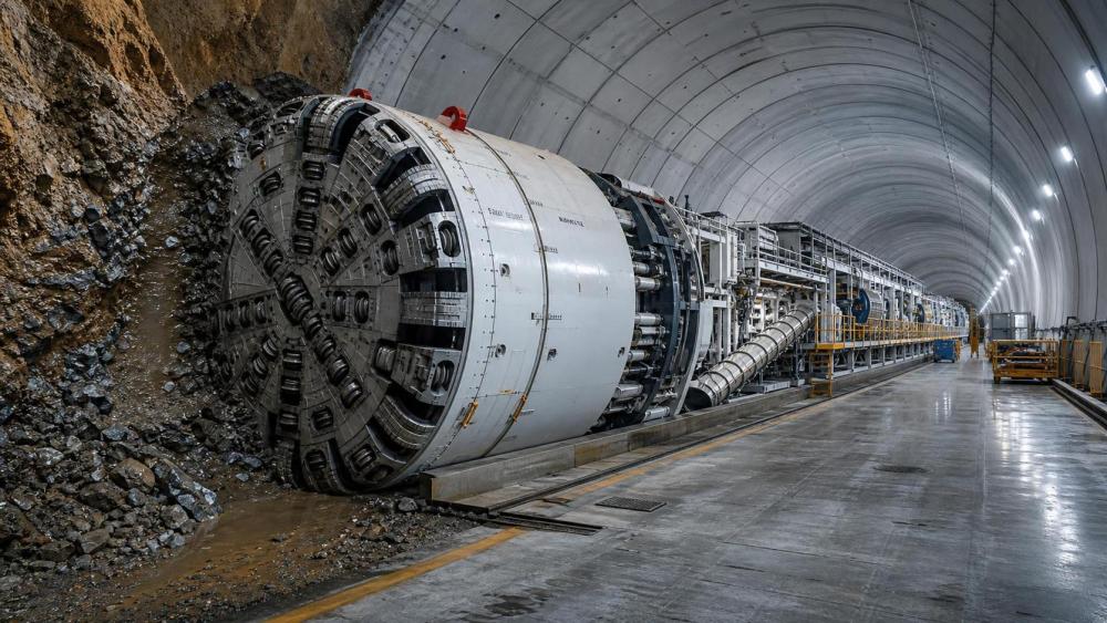
Hard-rock tunnel boring machines are generally suited to continuous, reasonably competent rock where disc cutters can maintain a predictable penetration rate. Selection should consider uniaxial compressive strength, brittleness, cutterhead opening ratio, disc cutter diameter, cutter spacing, installed torque, thrust capacity, and the ability to remove broken rock without choking the cutterhead. High strength alone does not define difficulty. Highly abrasive quartz-rich rock can consume cutters quickly, while blocky rock may create impact loading and uneven cutter wear even at moderate strength.
For fractured rock, a machine needs enough structural margin to cope with unstable blocks and frequent intervention risk. Shield configuration, ground support compatibility, probe drilling locations, and access to the cutterhead deserve equal attention with headline power figures. An open hard-rock machine may perform well where the rock mass remains self-supporting long enough for systematic bolting and shotcrete. Where squeezing, ravelling, or water ingress may close the excavation margin, a shielded arrangement with appropriate support installation capability can reduce exposure, provided the shield does not become vulnerable to jamming under convergent ground pressure.
Mixed-face tunnels require particular caution. A face split between hard rock and weak soil can induce asymmetric loads, steering difficulty, and uneven tool consumption. Cutterhead design should be assessed for both cutting and soil conditioning duties, with a realistic plan for changing tools and managing spoil. A machine that performs acceptably in each material separately may still struggle at their interface because thrust, torque, advance rate, and face pressure requirements change at the same time.
Where drill-and-blast excavation is being considered, the decision should account for the actual cycle time rather than nominal drilling speed. Drilling jumbo configuration depends on tunnel profile, drill pattern density, rock hardness, available boom coverage, and the need to perform bolting alongside production drilling. Feed length, hammer power, rod handling, positioning accuracy, dust control, and access for charging, mucking, scaling, and support installation all affect the achievable round length. Drill-and-blast can accommodate changing geometry and difficult transitions, but its logistics discipline must be strong enough to prevent the cycle from fragmenting into repeated delays.
Groundwater Changes the Machine Requirement
Water is often the factor that turns an apparently suitable machine into a high-risk selection. The relevant questions are not limited to whether groundwater is present. Its pressure, inflow path, fines content, chemical composition, temperature, and response to drawdown influence the excavation method, sealing arrangement, dewatering capacity, and maintenance interval.
In permeable granular ground under pressure, face support and controlled spoil removal are central. Earth pressure balance equipment depends on conditioned material forming a plastic, low-permeability plug in the working chamber and screw conveyor. Soil grading, clay fraction, water content, and boulder content should be reviewed against the likely conditioning response. Foam, polymers, and anti-clay agents may be necessary, but their consumption, storage, injection points, and compatibility with spoil handling must be planned before mobilization.
Slurry systems can be appropriate where groundwater control and face stability demand a pressurized slurry circuit, particularly in sand, gravel, or mixed granular deposits. Their selection brings a separate processing requirement: separation plant capacity, screen and cyclone arrangement, slurry lines, pumping head, settlement management, and disposal or reuse routes. A slurry machine should not be evaluated as a standalone shield. The separation plant and its operating envelope are part of the excavation system, and inadequate treatment capacity can stop advance even when the machine itself is mechanically available.
In rock tunnels, localized high-pressure inflows may require pre-excavation grouting, probe holes, drainage holes, or temporary pressure management. Equipment layout needs space and services for these activities. A machine with no practical way to drill ahead, inject grout, or safely inspect the face can create a costly constraint when water-bearing fractures are encountered. Corrosion resistance of piping, pumps, seals, electrical enclosures, and hydraulic components should be reviewed where aggressive water chemistry is possible.
Geometry, Access, and Logistics Set Real Limits
Tunnel diameter, curve radius, gradient, cross passages, shaft dimensions, and portal access determine whether machinery can be assembled, launched, supplied, maintained, and retrieved. A suitable cutterhead is of little value if the main drive, shield sections, backup gantries, or pipe-jacking jacks cannot be transported through the available route. Early transport studies should include component weights, lifting points, crane reach, trailer turning paths, shaft loading limits, and any restrictions on nighttime or urban delivery.
Pipe jacking machinery must be selected as a complete drive package: jacking frame, thrust wall, intermediate jacking stations, lubrication system, guidance equipment, spoil transport, reception arrangement, and pipe joint capacity. Long drives can impose high friction loads even in apparently favorable ground. Bentonite lubrication may reduce external friction, but it requires annulus control and an injection arrangement that remains effective through changes in soil. Pipe material, joint geometry, allowable compressive load, alignment tolerance, and the possibility of stoppages should be assessed together. A drive that approaches the pipe's permissible jacking load leaves little room for unexpected ground resistance.
Gradient has a direct effect on muck transport and water management. Conveyor systems can offer continuous removal in long drives, but transfer points, belt cleaning, emergency stopping, and maintenance access must suit wet, abrasive spoil. Rail systems require turning and passing arrangements, while rubber-tyred haulage depends on roadway width, ventilation, traction, and interaction with other underground activities. In steep mining or tunnel access headings, braking capacity and heat management deserve as much review as tractive effort.
Use Parameters That Reflect the Actual Duty
Supplier data sheets often present installed power, maximum torque, maximum thrust, penetration rate, and nominal production capacity. These figures are useful only when interpreted alongside duty cycle and ground assumptions. Maximum thrust may be available for a limited operating condition; continuous torque can differ from peak torque; penetration performance depends on cutter condition, rock confinement, and removal of cuttings. Requesting load curves, hydraulic diagrams, thermal limits, and maintenance intervals makes it easier to distinguish design capability from an optimistic headline figure.
For a full-face machine, review at least the following relationships:
- Cutterhead torque against the expected strength and abrasivity range, including the margin needed when tools are worn or the face becomes uneven.
- Thrust capacity relative to cutter penetration demand, segment ring resistance where relevant, and the friction generated by a shield moving through convergent ground.
- Installed conveyor, screw, slurry, or rail haulage capacity against the volume of excavated material and the likely moisture condition of spoil.
- Probe drilling and ground treatment interfaces, especially where weak zones, water inflow, or voids could interrupt normal advance.
- Electrical supply quality, ventilation capacity, cooling water, compressed air, and drainage, since undersized site services can limit a correctly specified machine.
The same discipline applies to auxiliary equipment. A drilling jumbo requires booms that reach the complete profile without excessive repositioning, while a bolter needs suitable feed geometry for the support pattern. Underground load-haul-dump equipment must fit the tunnel clearance with allowance for articulation, dump height, passing bays, and cable or battery infrastructure. Battery-electric equipment can reduce heat and exhaust in confined workings, but charging or swapping locations, electrical redundancy, fire response arrangements, and battery handling routes must be resolved before deployment.
Plan for Transitions and Interventions
Variable ground conditions usually expose weaknesses during transitions, not in the long uniform sections used to demonstrate performance. The procurement scope should therefore include a transition operating philosophy. It should define trigger conditions for reducing advance rate, changing cutter inspection frequency, increasing face support, starting probe drilling, modifying soil conditioning, or installing additional ground support. These decisions need measured inputs such as cutterhead torque, thrust, chamber pressure, conveyor current, penetration rate, water inflow, and settlement readings, rather than reliance on a single alarm threshold.
Tool intervention strategy deserves early engineering. Cutter change access, hyperbaric capability where pressurized intervention could be required, lock procedures, lifting aids, storage for replacement tools, and time needed to reach the cutterhead all affect exposure and schedule. In abrasive rock, holding an appropriate stock of disc cutters, cutter rings, scraper tools, seals, hoses, and critical bearings can be more valuable than minimizing initial spares. The stock level should be based on expected wear mechanisms and replenishment lead time, not a generic package list.
Wear protection should be considered across the whole spoil path. Chutes, hoppers, screw conveyors, slurry lines, crusher surfaces, and transfer points may see severe abrasion. Replaceable liners, hardfacing, access doors, and lifting provisions reduce the duration of maintenance work. However, hard materials should be selected with the expected impact regime in mind; a highly wear-resistant liner may be vulnerable to cracking where large rock fragments strike repeatedly.
Commercial Comparison Should Include Interface Risk
Purchase price does not describe the full cost of tunnel construction machinery. A useful comparison separates fixed equipment cost from ground-dependent operating exposure. The latter includes cutter and tool consumption, conditioning materials, power demand, slurry treatment, dewatering, spare parts, specialist personnel, support equipment, and lost time during interventions. Assumptions behind each allowance should be visible, particularly where geology is uncertain.
Contract boundaries require careful definition. The machine supplier, segment supplier, civil contractor, power provider, ventilation installer, spoil handler, and instrumentation contractor may each control part of a system that must operate as one. Interfaces commonly fail around electrical connection points, communications protocols, plant foundations, lifting equipment, data ownership, and acceptance testing. A responsibility matrix should state who designs, supplies, installs, tests, and maintains each interface, including temporary works required for launch and reception.
Factory acceptance testing should verify more than basic motion. Where practical, it should cover control logic, alarms, emergency stops, instrumentation signals, remote diagnostics, hydraulic leak checks, and the integration of major subsystems. Site commissioning then needs enough time to validate conveyor or slurry flow, segment handling, guidance, ventilation, dewatering, and communication under working conditions. A rushed launch can conceal interface defects until recovery becomes much harder.
Keep the Selection Adaptable
The strongest equipment decision is supported by defined contingencies rather than confidence that the ground model will be exact. Alternative cutterhead tools, spare shield sealing components, additional pump capacity, grouting connections, haulage options, and adaptable support arrangements can provide practical recovery paths. These provisions should be proportionate to the uncertainty and physically compatible with the selected machine.
Before release, the selected configuration should be tested against the difficult chainages: the wet granular reach, the hard abrasive band, the mixed-face transition, the tight curve, the steep section, and the location where maintenance access is poorest. If the machine, its backup systems, and the site logistics can work through those conditions with defined controls, the selection has a defensible basis for the remainder of the alignment.
Related News
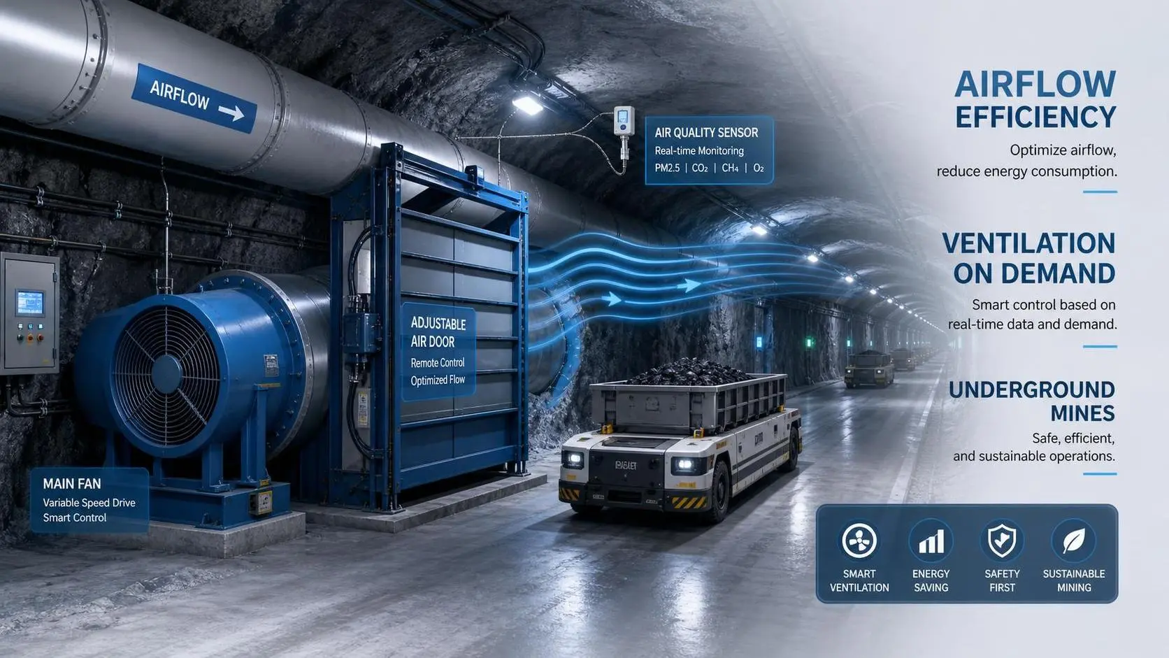
How Ventilation on Demand Improves Airflow Efficiency in Underground Mines
Mine Ventilation Solutions made smarter: see how ventilation on demand boosts airflow efficiency in underground mines, cuts energy waste, and supports safer, more productive operations.
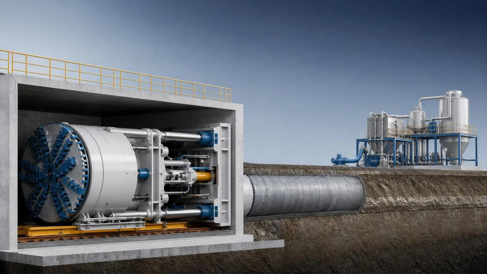
How to Evaluate Pipe Jacking Equipment for Municipal Sewer and Utility Projects
Pipe jacking equipment for municipal projects: learn how to compare machine type, steering, spoil handling, safety, and lifecycle cost for reliable sewer and utility installation.
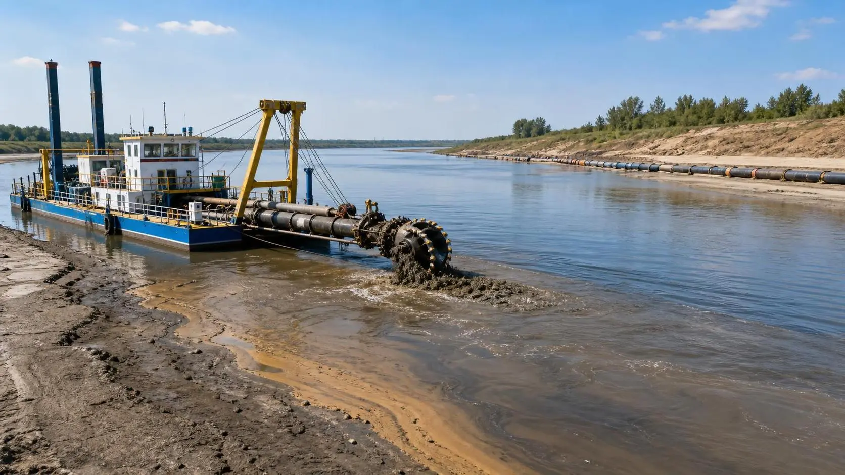
How YLCSD300 Cutter Suction Dredger Parameters Affect River Dredging Output
YLCSD300 cutter suction dredger output depends on cutter, pump, pipe, depth, and hull balance. Learn how river conditions shape real dredging performance before you buy.
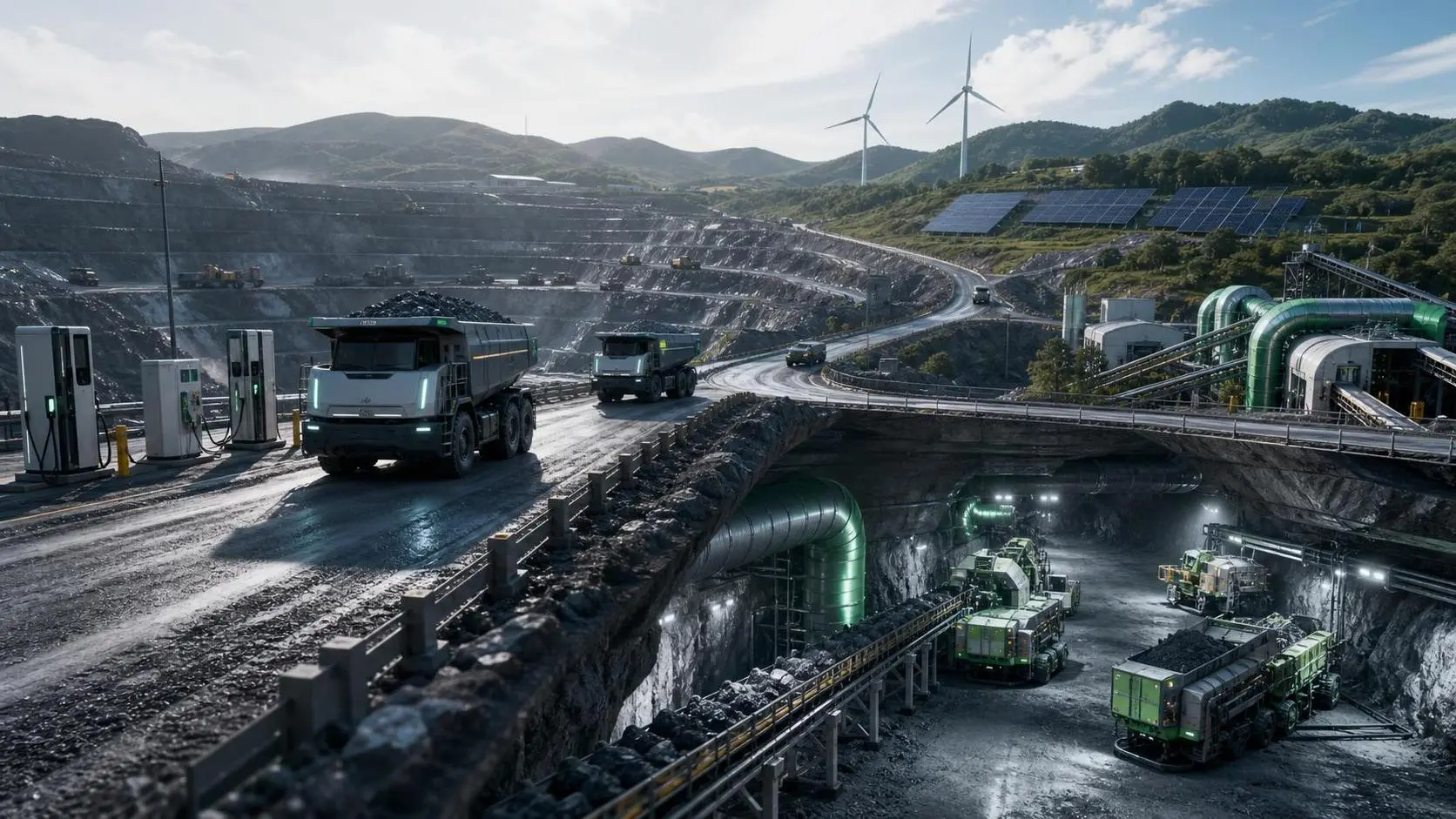
What Should a Mine Decarbonization Roadmap Include to Cut Emissions Without Hurting Output?
Mine decarbonization roadmap essentials: learn how to cut mining emissions with phased electrification, ventilation planning, and infrastructure readiness—without sacrificing output.
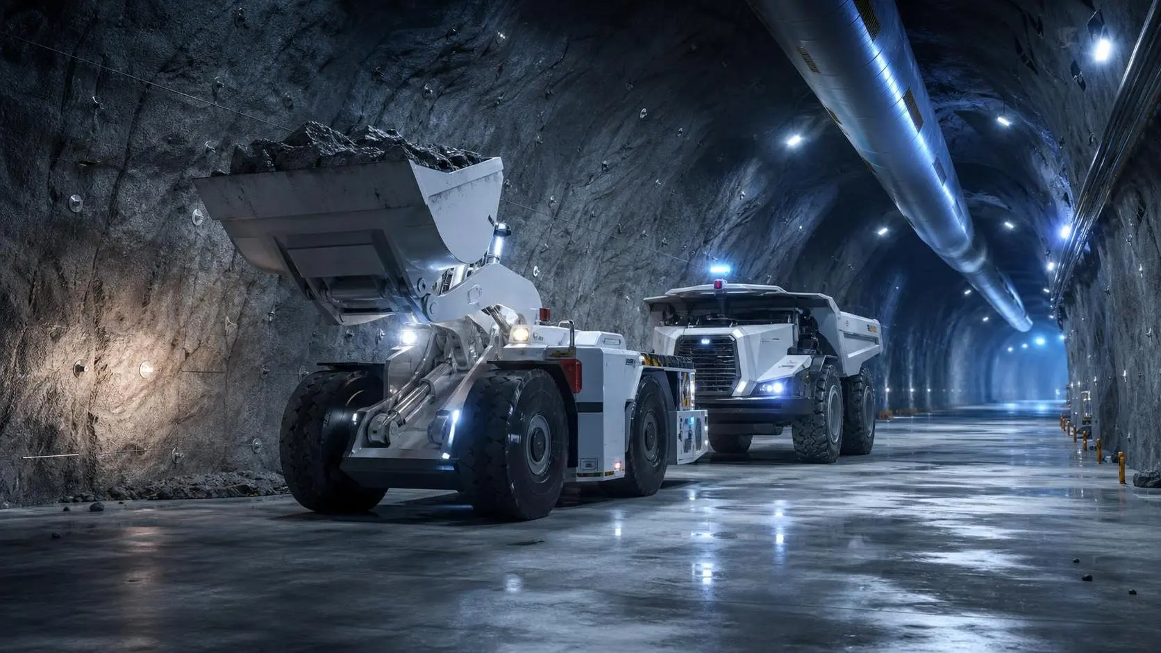
How to Evaluate Underground Mine Automation Companies for Safety and ROI
Underground mine automation companies vary widely in safety, interoperability, and ROI. Learn how to compare vendors, reduce deployment risk, and choose a scalable solution.
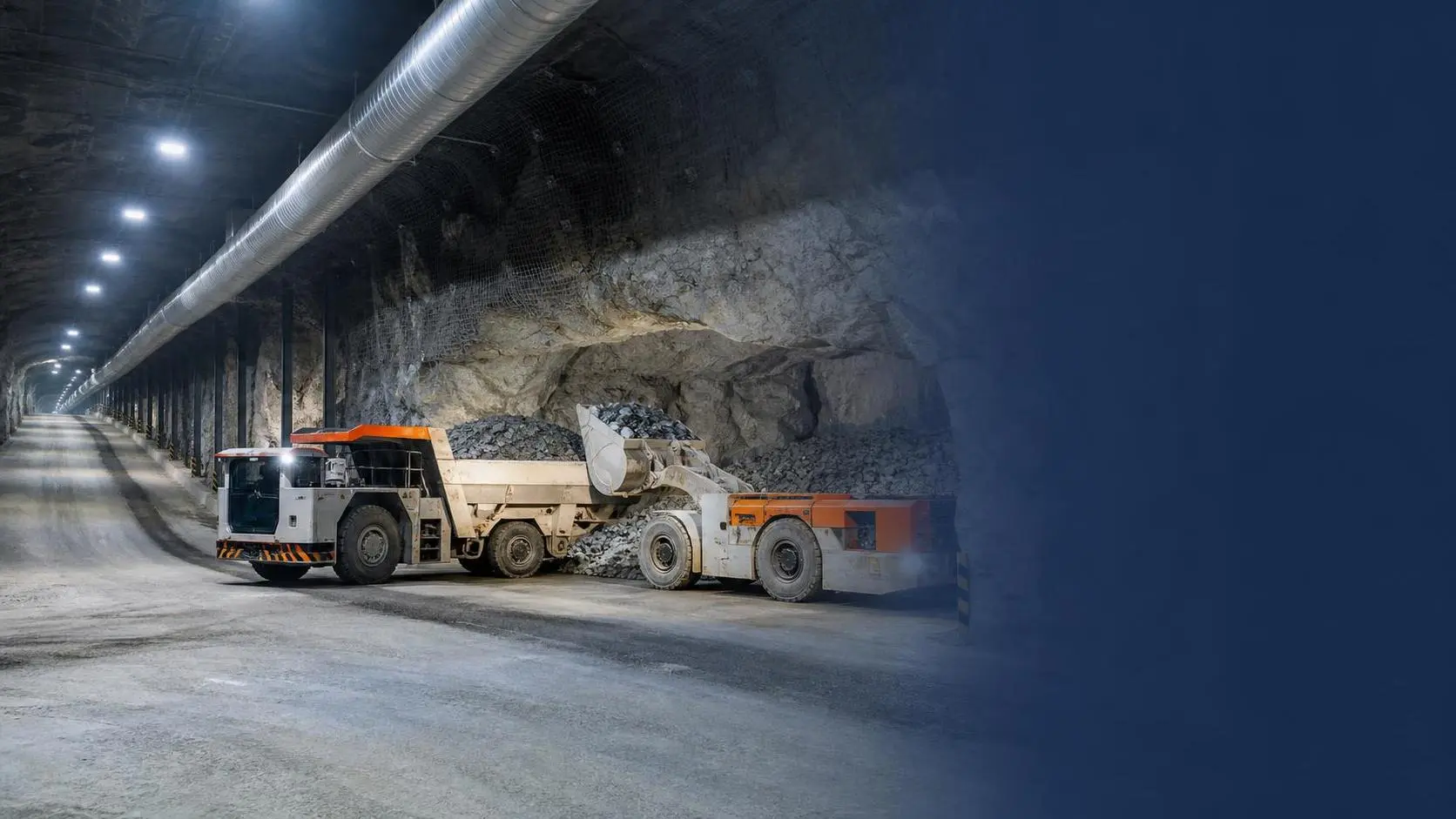
How to Evaluate Underground Haulage Systems for Ore Output, Ramp Grade, and Ventilation Limits
Underground haulage systems should be evaluated by ore output, ramp grade, and ventilation limits—not brochures. Learn how to compare trucks, LHDs, and electric options for smarter mine planning.
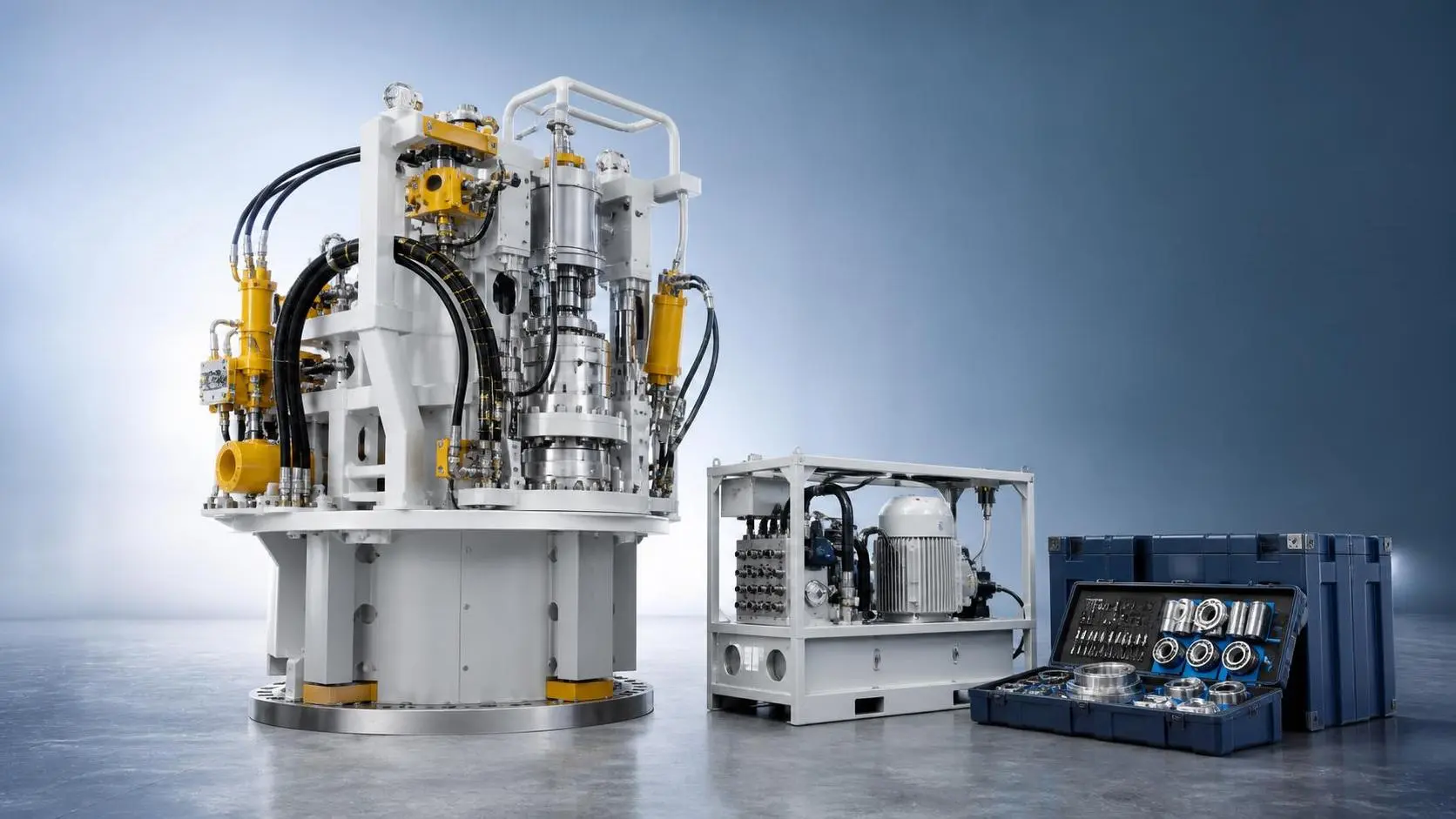
How to Evaluate a Pipe Jacking Equipment Distributor for Project Support and Uptime
Pipe jacking equipment distributor evaluation made practical: learn how to assess parts support, service response, training, and technical readiness to reduce downtime and protect project uptime.
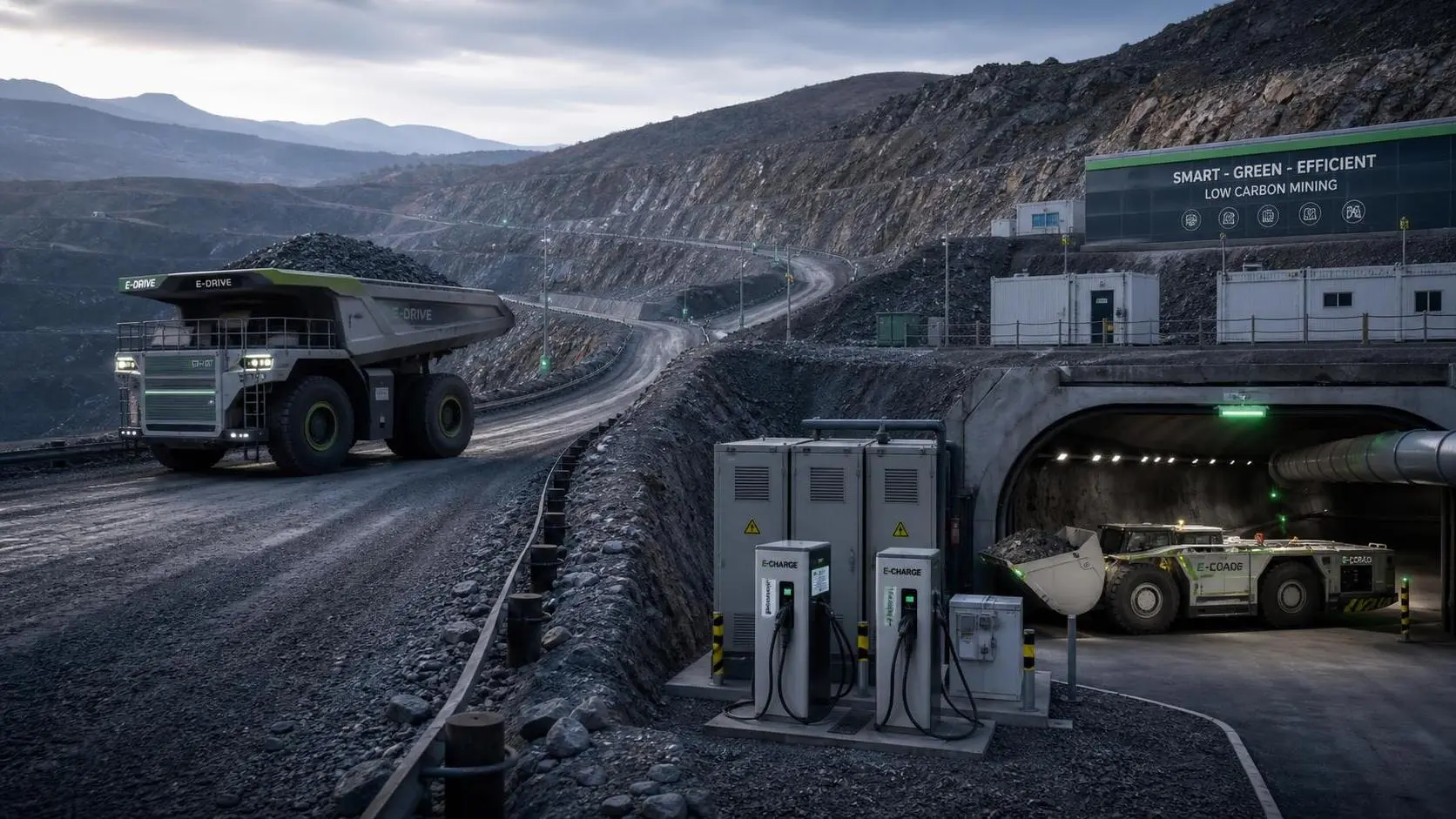
How to Build a Mining Decarbonization Strategy That Balances Emissions, Cost, and Fleet Reality
Mining decarbonization strategy starts with fleet reality. Learn how to cut emissions, control cost, and align power, ventilation, and production for a practical mine transition.
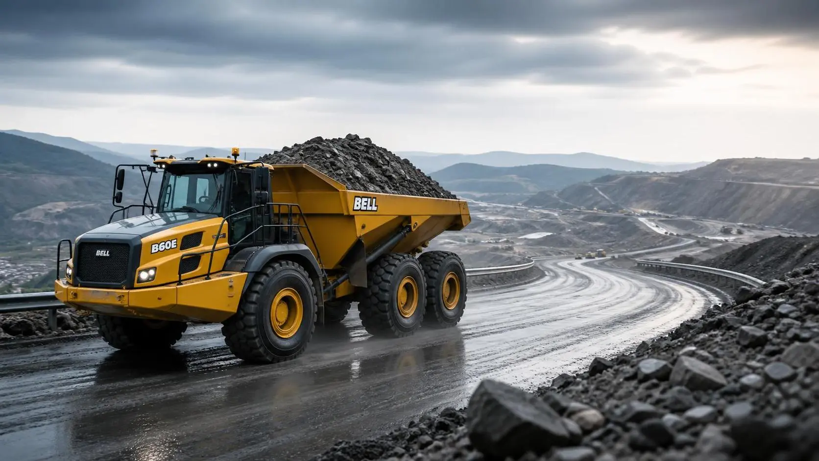
How to Evaluate Articulated Dump Trucks Payload for Haul Road Conditions and Cycle Efficiency
Articulated Dump Trucks payload evaluation starts with real haul road conditions, not brochure numbers. Learn how to balance payload, traction, grades, and cycle efficiency for safer, higher output.
Related News
- 00
0000-00
Selecting Tunnel Construction Machinery for Variable Ground Conditions - 00
0000-00
How Ventilation on Demand Improves Airflow Efficiency in Underground Mines - 00
0000-00
How to Evaluate Pipe Jacking Equipment for Municipal Sewer and Utility Projects - 00
0000-00
How YLCSD300 Cutter Suction Dredger Parameters Affect River Dredging Output - 00
0000-00
What Should a Mine Decarbonization Roadmap Include to Cut Emissions Without Hurting Output?
Weekly Insights
Stay ahead with our curated technology reports delivered every Monday.