
Water Diversion Tunnel Lining: Concrete vs. Steel for High-Pressure Service





Concrete is a credible choice for high-pressure water diversion tunnels when the surrounding rock can safely participate in carrying pressure and leakage remains controlled. Steel becomes more compelling where a continuous pressure barrier is needed, confinement is inadequate, or leakage could destabilize the ground. The decision depends on the complete tunnel system: lining, rock mass, groundwater, joints, and the loads that occur during filling, operation, shutdown, and maintenance.
Selecting water diversion tunnel lining by concrete strength or steel thickness alone misses the main failure mechanisms. A strong concrete lining can crack and transmit pressure into rock joints. A steel liner designed for internal pressure can buckle when the tunnel is emptied and groundwater acts from outside. Both materials require an explicit design for how loads reach the surrounding ground.
Define the pressure conditions before comparing materials
Operating pressure is only one part of the design envelope. Water hammer from valve movements, pump trips, or other operational changes can produce pressure peaks and low-pressure events that govern lining design. Their magnitude depends on the hydraulic system, including tunnel length, flow velocity, surge-control arrangements, and operating procedures.
The opposite loading direction also matters. When the tunnel is drained, internal water pressure disappears while groundwater pressure may remain. This condition can govern steel-liner stability and affect concrete linings, joints, and drainage provisions. Construction stages can introduce additional loads before the completed system develops its intended support.
Establish these conditions for each tunnel reach:
- Internal pressure envelope: normal operation, hydraulic transients, filling, dewatering, and potential vacuum conditions.
- External water pressure: groundwater conditions during operation and shutdown, including credible drainage blockage.
- Ground behavior: in-situ stresses, rock stiffness, jointing, permeability, faults, and connections to slopes or the surface.
- Performance limits: acceptable leakage, ground movement, maintenance access, and consequences of an outage.
A single pressure rating for the entire alignment can conceal significant differences. A deep reach in competent rock and a shallow reach near a valley side may require different lining systems even when their internal water pressures are similar.
Concrete and steel perform different roles
A concrete lining provides structural support, a hydraulic surface, and protection against deterioration of exposed ground. In pressure service, its behavior depends on interaction with the surrounding rock. Internal pressure causes outward deformation, and some load can transfer into the rock where contact and ground stiffness permit.
Concrete has limited tensile capacity. Reinforcement helps control crack distribution and width, but reinforced concrete should not automatically be treated as watertight under pressure. Construction joints, segment joints, penetrations, and local defects can become leakage paths even where the concrete itself has low permeability.
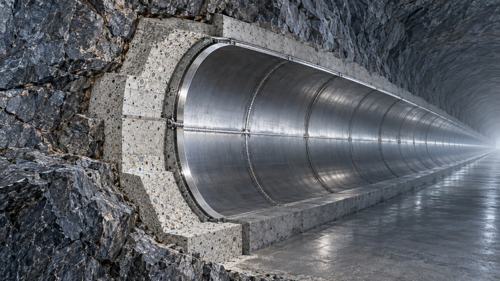
A welded steel liner provides a continuous pressure boundary. It is commonly embedded within concrete, which transfers loads and provides support. Depending on the design, the steel may resist internal pressure largely on its own or share load with the surrounding concrete and rock. Any assumed sharing must account for gaps, cracking, deformation compatibility, and construction tolerances.
Consequently, the practical choice is often between a concrete pressure tunnel and a steel-lined concrete tunnel. Specifying steel does not remove the need to design the backing concrete, contact grouting, surrounding ground, or external-pressure resistance.
When concrete is a defensible choice
Concrete becomes attractive where the rock mass has adequate confinement, predictable deformation, and manageable permeability. Under those conditions, the lining and rock can function as an engineered system, with reinforcement and joint details selected to keep cracking and leakage within acceptable limits.
The geological assessment must go beyond rock strength. Hard rock can contain open joints, weathered seams, or faults that provide pressure pathways. Conversely, a fractured rock mass may still offer useful confinement, although its permeability and deformation require careful treatment.
Rock cover alone does not establish pressure-tunnel suitability. Topography, stress orientation, valley geometry, and discontinuities influence whether internal water pressure could open existing joints or create fractures. Assess hydraulic jacking and hydraulic fracturing using the local stress state and groundwater conditions. Leakage that raises pressure along a discontinuity can reduce its effective clamping and affect stability beyond the tunnel wall.
Concrete is therefore a stronger candidate when limited leakage has acceptable consequences and the ground can safely accommodate the resulting pressure distribution. Its case weakens near shallow cover, sensitive slopes, connected aquifers, or structures that could be affected by seepage.
Joint design also changes the assessment. A TBM segmental lining introduces repeated joints whose behavior depends on gasket compression, tolerances, joint opening, and pressure direction. Segment strength alone does not establish suitability for high-pressure conveyance. Some projects require a secondary lining or another engineered containment layer.
Where steel earns its additional complexity
Steel deserves close consideration where pressure containment must remain reliable despite uncertain or insufficient rock confinement. Typical candidates include shallow pressure reaches, weak zones, approaches to portals, and sections where leakage could threaten ground stability or adjacent assets.
The reason is the continuity of the barrier. Properly designed and executed welds allow the liner to carry circumferential tension while limiting water entry into the surrounding ground. That benefit depends on complete detailing at branches, penetrations, closures, and transitions.
For preliminary understanding, the hoop stress in a thin cylindrical steel shell increases with internal pressure and diameter and decreases with wall thickness. Final design must address more than this relationship: material properties, weld details, geometric discontinuities, cyclic loading, corrosion provisions, and any credited support from the surrounding system.
Pressure cycles deserve particular attention near branches, stiffeners, and other stress concentrations. A liner that satisfies a static stress check may still need fatigue assessment where frequent operational changes create repeated stress ranges.
Steel also brings installation constraints. Plate sections or fabricated cans must reach the workface, be aligned, welded, examined, and backed with concrete in a restricted environment. Tunnel access, ventilation, lifting capacity, and the sequence of closure welds can determine whether an otherwise sound concept is practical.
The drained tunnel can govern steel-liner design
Internal pressure tends to hold a steel liner outward against its backing. During dewatering, groundwater can act inward while the shell has little internal support from water pressure. Buckling resistance then depends strongly on liner geometry, imperfections, stiffening, gaps, and the restraint provided by the backing system.
Backing concrete should not be assumed to provide perfect continuous contact. Shrinkage, temperature changes, incomplete grouting, or placement defects can leave gaps. These conditions affect the support available to the liner and must be reflected in design assumptions and acceptance criteria.
Drainage can reduce external pressure, but it creates an operational dependency. Drains can clog, become inaccessible, or lose effectiveness. A design that credits pressure relief needs a defined maintenance strategy and an assessment of degraded or unavailable drainage.
The same scrutiny applies to grouting. Contact grouting fills voids and improves load transfer; consolidation grouting treats selected rock features. Neither automatically turns an inadequately confined reach into a reliable pressure tunnel.
Compare construction quality and lifetime intervention
The economical option is the system that can be built consistently and maintained within the project’s outage constraints. Initial material quantities provide only a partial comparison.
For concrete, quality control should focus on placement continuity, consolidation, curing, thermal cracking, construction joints, waterstops, and voids behind the lining. High compressive strength cannot compensate for a poorly sealed joint or inadequate contact with the ground. Repairs may require injection work, local reconstruction, or repeated access if the leakage mechanism remains active.
For steel, the construction plan should connect material traceability, welding procedures, inspection access, weld examination, coating application, and repair acceptance. Backing concrete and grouting need equal attention because the completed liner depends on their support. Pressure testing and controlled filling should follow a project-specific plan that considers the tunnel system and surrounding ground.
Corrosion assessment should distinguish the water-facing surface from the embedded exterior. Water chemistry, sediment, oxygen availability, coating condition, and access influence the protection strategy. Abrasive sediment can also damage concrete surfaces or protective coatings, particularly where local flow disturbances increase wear.
Hydraulic performance belongs in the cost comparison. Finished diameter, surface condition, joint details, and local transitions affect head loss. A smoother surface may offer an advantage, but coating deterioration, deposits, and reduced internal diameter can change the lifetime result. Compare completed geometries and realistic operating conditions.
Select by tunnel reach, then resolve the interfaces
A mixed lining strategy can suit an alignment whose geological and hydraulic conditions vary. Concrete may serve well-confined reaches, while steel provides containment through sections with unfavorable confinement or unacceptable leakage consequences.
The interfaces require their own design. A steel-to-concrete transition changes stiffness, deformation, pressure containment, and load transfer. Water can seek a path around the end of the steel liner unless the termination and surrounding sealing measures address that route. The transition should sit where suitable ground conditions can support the detail, with access and construction sequencing considered.
A practical selection process follows four decisions:
- Map the pressure and ground conditions. Divide the alignment into reaches with comparable hydraulic loads, confinement, permeability, and failure consequences.
- Test concrete feasibility. Establish whether cracking, leakage, joint behavior, and pressure transfer into the rock remain acceptable.
- Develop steel alternatives where needed. Check internal pressure, external-pressure buckling, fatigue where relevant, corrosion, and installation feasibility.
- Compare complete systems. Include ground treatment, backing, transitions, inspection, maintenance, outage exposure, and repair access.
Before approving a water diversion tunnel lining, require the design basis to state which components carry each load, what leakage is acceptable, and what happens during dewatering. Construction acceptance criteria must then support those assumptions. The preferred solution is the one whose pressure containment, ground interaction, and maintenance requirements remain credible throughout the operating cycle.
Related News
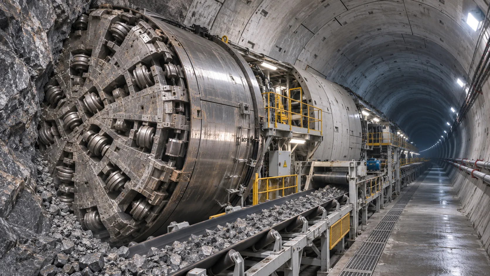
How TBM Excavation Works in Rock and Soft Ground: A Practical Guide
TBM Excavation in rock and soft ground explained: compare machine types, ground support, spoil removal, and the factors that guide smarter project planning.
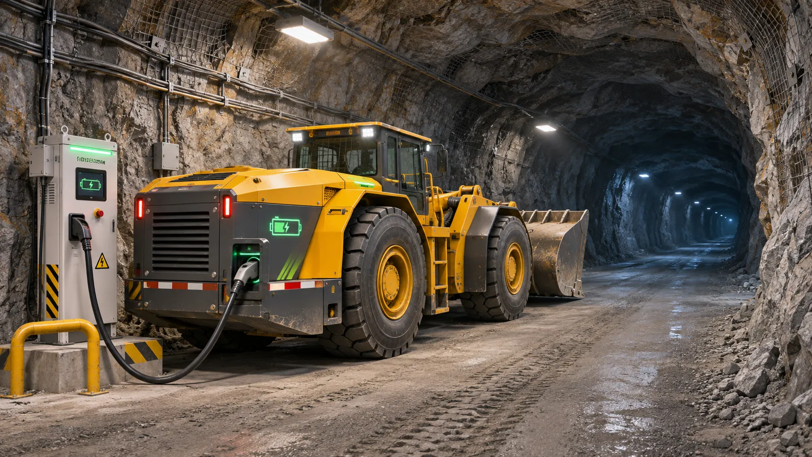
Choosing a Zero-Emission Underground Equipment Supplier: What to Check
Choosing a zero emission underground equipment supplier? Compare duty-cycle performance, charging, safety, total costs and support before you commit.
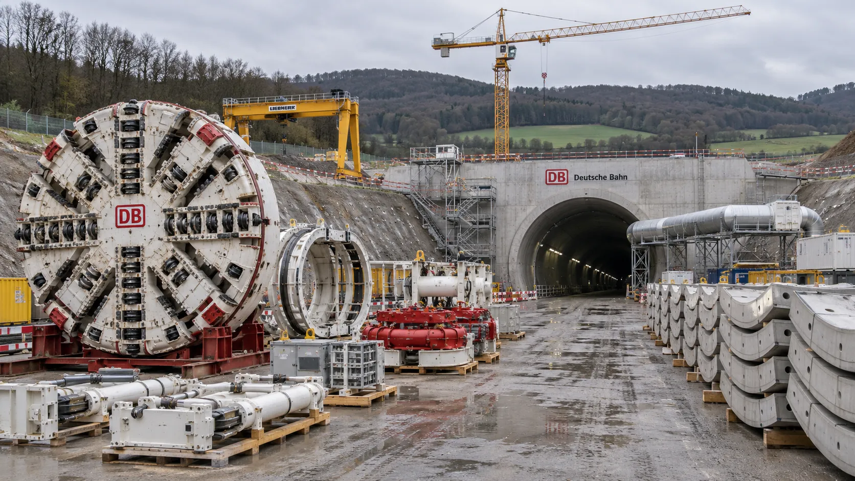
Construction Starts on Germany's Pfaffensteig Rail Tunnel, With Two TBMs Planned
Pfaffensteig rail tunnel construction is underway in Germany. Discover how two planned TBMs will support the 11-kilometre project near Stuttgart.
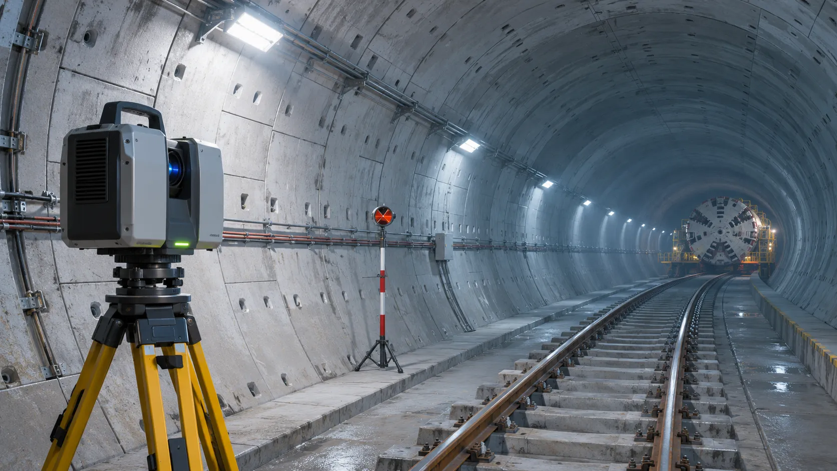
How Real-Time Underground Mapping Systems Work in Tunneling
Discover how real-time underground mapping systems guide tunneling teams, integrate sensor data, and support confident decisions with verified accuracy.
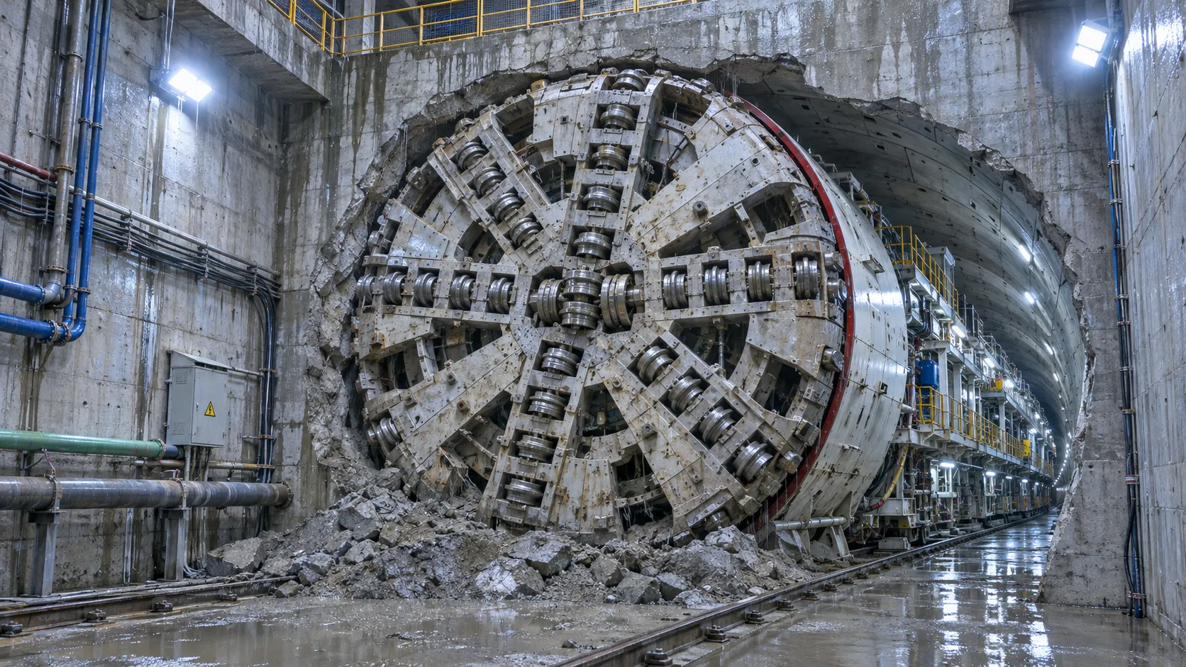
First Mechanized Tunnel Crossing Beneath the Panama Canal Completed
Panama Canal tunnel crossing: Explore the reported Metro Line 3 milestone and what it could mean for future underwater tunneling projects.
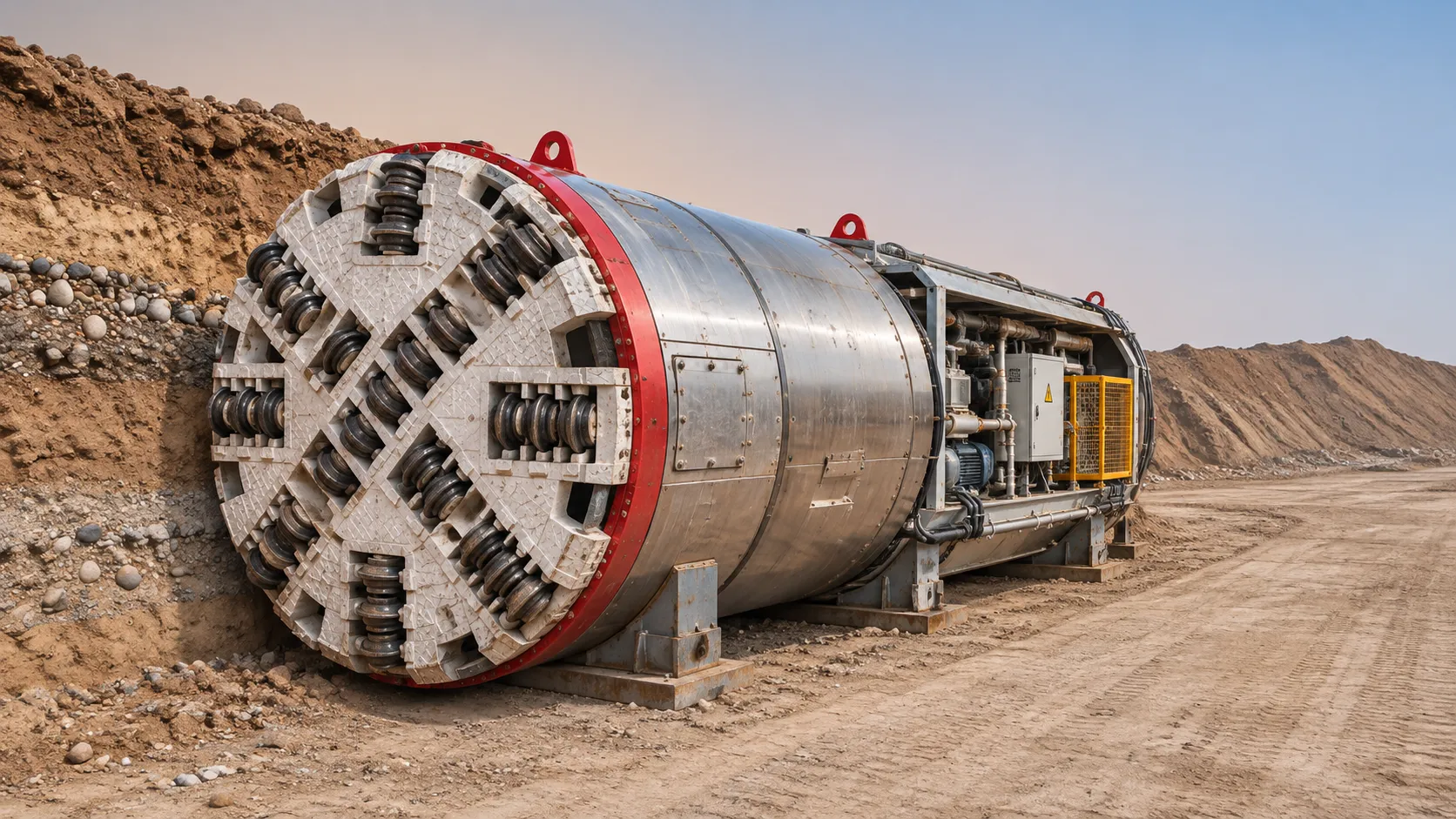
Underground Utility Construction Equipment: Choosing by Ground Conditions
Choose underground utility construction equipment with confidence. Compare trenching, HDD, microtunnelling and TBMs by ground conditions, risk and cost.
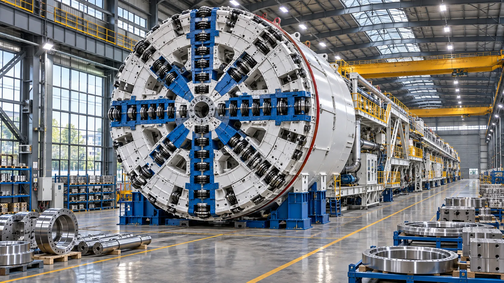
China Sets Tunnel Boring Machine Export Controls as India Pushes Local Production
China tunnel boring machine export controls could reshape procurement as India pushes local production. Explore potential supply and project impacts.
Choosing a Trenchless Pipeline Installation Contractor: Key Qualifications
Choose a trenchless pipeline installation contractor with confidence. Learn how to assess experience, equipment, safety, costs, and project risks before you hire.
China's 70% TBM Share and Export Controls Challenge India's Local Production
China's TBM export controls could challenge India's local production and infrastructure sourcing. Explore the potential risks and procurement options.
Related News
- 00
0000-00
How TBM Excavation Works in Rock and Soft Ground: A Practical Guide - 00
0000-00
Choosing a Zero-Emission Underground Equipment Supplier: What to Check - 00
0000-00
Construction Starts on Germany's Pfaffensteig Rail Tunnel, With Two TBMs Planned - 00
0000-00
How Real-Time Underground Mapping Systems Work in Tunneling - 00
0000-00
First Mechanized Tunnel Crossing Beneath the Panama Canal Completed
Weekly Insights
Stay ahead with our curated technology reports delivered every Monday.