
What Ventilation System Is Best for Long-Distance Tunnel Construction?





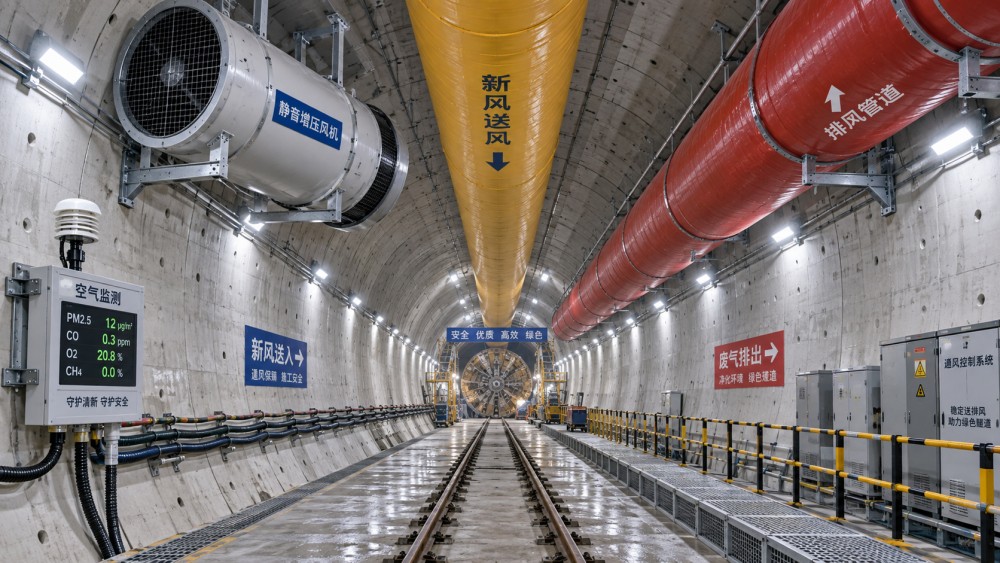
For a long-distance tunnel, the best ventilation arrangement is usually a high-capacity forced system with a dedicated fresh-air duct extending as close as practical to the advancing face, supported by staged booster fans and continuous atmospheric monitoring. Where dust, heat, diesel exhaust, methane, blasting fumes, or a long single-entry alignment create a heavier ventilation burden, a hybrid arrangement that combines forced supply with controlled exhaust is often the stronger choice.
No single fan or duct type is automatically suitable for every long drive. The workable design comes from matching airflow quantity, pressure capability, duct resistance, face emissions, and the tunnel's changing geometry. A system that delivers enough air near the portal can still fail at the face if leakage, damaged duct joints, sharp bends, equipment obstructions, or an undersized fan consume the available pressure.
Why Forced Ventilation Is Usually the Starting Point
Forced ventilation pushes clean air from the portal or ventilation shaft through a duct toward the work area. It is widely used because it supplies breathable air directly to the zone where excavation, mucking, segment handling, drilling, or ground support work occurs. In a TBM tunnel, the duct discharge is positioned to sweep the working area without creating an uncomfortable high-velocity jet around personnel or disrupting dust capture points.
The fresh-air stream also dilutes contaminants generated at the face. These can include respirable dust from cutterhead excavation, silica-bearing fines in hard-rock work, welding fumes, hydraulic-oil mist, blasting gases in drill-and-blast headings, and emissions from diesel-powered loaders, haulage vehicles, and support equipment. Air delivered only to the tunnel entrance has little value when the active heading is far inside the excavation.
For a relatively straightforward, single-heading excavation with a stable ventilation route, a forced duct system is often the most practical foundation. It is easier to extend as the heading advances than a full return-air installation, and it keeps the main ventilation equipment outside the immediate excavation zone. Its limitation appears as the tunnel gets longer: every added duct section increases friction loss, while every poor coupling or tear reduces the air that actually reaches the face.
When a Hybrid Supply-and-Exhaust System Is Better
A hybrid system uses one airflow path to supply clean air and another to remove contaminated air from a defined source or zone. It is particularly useful where simply diluting pollution would require excessive airflow, or where contaminants need to be controlled before they spread through the tunnel.
At a TBM heading, local extraction can be connected to cutterhead dust collection, transfer-point enclosures, belt conveyor transfer zones, or slurry-treatment interfaces. In drill-and-blast work, exhaust control becomes valuable after firing, when fumes must be cleared from the face before re-entry. In tunnels with frequent diesel activity, a defined return path can prevent exhaust from lingering around loading areas or moving toward occupied workstations.
The arrangement must be balanced carefully. Excessive extraction near the face can pull dusty air through areas meant to remain cleaner. A supply duct placed too close to an exhaust pickup can create a short circuit, with fresh air leaving before it sweeps the working zone. The target is a predictable air path: clean air enters where people and critical equipment need it, passes through the contamination zone, and exits through an intentional return route.
Length Changes the Problem from Air Quantity to Pressure Management
Long-distance tunnel ventilation is frequently misjudged by focusing only on fan airflow rating. A fan may be advertised with a high free-air volume, yet that volume drops substantially when it must overcome the resistance of many hundreds or thousands of metres of ducting. The operating point is determined by the intersection of the fan curve and the resistance of the actual system, not by the largest number printed on a fan nameplate.
Pressure loss rises with air velocity, duct length, bends, branch connections, obstructions, and rough or deformed duct surfaces. A design that uses a smaller duct to achieve a faster jet at the discharge end can become inefficient over a long distance because velocity-related losses grow quickly. A larger duct often reduces resistance and leakage sensitivity, though it occupies more tunnel space, requires stronger suspension, and may interfere with rail, conveyor, pipe, cable, or vehicle clearance.
Long runs therefore commonly need staged ventilation. Booster fans are installed at planned intervals so the main fan does not carry the full pressure burden alone. Their placement must follow the duct and fan design, because poorly coordinated boosters can destabilize flow, cause recirculation, overload a duct section, or make shutdown sequencing difficult. Each added fan also needs accessible power isolation, suitable mounting, vibration control, inspection clearance, and a reliable communications link to the ventilation control strategy.
Choose the Duct as Carefully as the Fan
Duct performance is not a minor installation detail. Flexible fabric ducting is common because it is light, quickly extended, and suited to changing tunnel alignment. Its effectiveness depends on fabric strength, coating, seam quality, fire performance appropriate to the project requirements, and the way it is hung. Sagging duct creates restrictions. Twisted sections and crushed portions create local losses. Leaks at couplings can turn an otherwise adequate fan selection into an under-ventilated face.
Rigid steel ducting provides a smoother, more durable air path and can be advantageous for long, relatively permanent runs. It is heavier to install, less forgiving around curves, and demands disciplined flange sealing. Mixed systems are also used: a durable rigid main run feeds flexible sections near the advancing face, where frequent extension and repositioning are unavoidable.
Airflow Should Be Calculated from the Actual Contaminant Load
Ventilation quantity must cover more than the tunnel volume. The face requires enough fresh air to dilute the worst credible contaminant source during the intended activity. For diesel equipment, this means examining engine power, duty cycle, equipment count, and whether several machines can operate simultaneously in the same ventilation district. For blasting, it means accounting for post-blast gases and the clearance period before work resumes. For mechanized excavation, the critical driver may be dust generation at the cutterhead or conveyor system rather than engine exhaust.
Heat is often treated as a secondary issue until the heading is deep enough for it to affect work pace and equipment reliability. Rock temperature, groundwater, electrical equipment, hydraulic systems, conveyors, and people all add heat. More airflow can improve conditions, but it is not a universal substitute for cooling. Warm incoming air, long duct heat gain, or high humidity can limit the benefit of increased volume. A ventilation design should distinguish between contaminant control and thermal control instead of assuming the same airflow adjustment solves both.
Humidity also changes how a system feels and performs. Water spray used for dust suppression can reduce airborne dust at its source while increasing moisture in the tunnel. Condensation inside ducts, wet surfaces around electrical equipment, and fogging near discharge points can follow. This does not make wet suppression unsuitable; it means the air-management plan must account for water, drainage, filtration, and visibility together.
Face Position and Air Distribution Matter
The final section of duct is where many otherwise sound systems lose effectiveness. If the outlet is too far from the heading, contaminated air can collect in the face area. If it is too close or aimed directly at freshly broken ground, the jet can resuspend settled dust and spread it through the work zone. The right standoff distance and discharge direction depend on the excavation method, tunnel cross-section, local extraction arrangement, and the location of machines and services.
Ventilation extensions should be coordinated with the excavation cycle. A delay after each advance gradually increases the unsupported distance between duct outlet and face. On a long project, small routine delays can produce repeated low-flow conditions before anyone identifies a major fault. Assigning a clear trigger for extending duct, checking couplings, and confirming airflow after each relocation avoids treating ventilation as an afterthought to production.
Where a tunnel branches, intersects a cross-passage, or changes section, airflow can split into paths that were not present in the original layout. A side opening may become a dead zone, while a leakage path may reduce the flow at the heading. Temporary bulkheads, regulators, doors, or auxiliary fans should be considered as part of the ventilation layout, not improvised only after poor readings appear.
Monitoring Turns a Design into a Working System
Continuous monitoring is especially valuable in long tunnels because conditions at the portal do not represent conditions at the face. Sensors should be located where they reveal the actual ventilation result: near the advancing work area, in return-air paths, around diesel activity, and at points where air may recirculate. The selected instruments should reflect the credible hazards, such as oxygen displacement, carbon monoxide, nitrogen oxides, combustible gas, dust, temperature, and airflow velocity.
Readings need context. A low airflow measurement can result from fan degradation, a blocked inlet, a collapsed duct section, a newly opened leakage point, an incorrectly positioned damper, or an unauthorized branch connection. Rising contaminants may instead indicate an equipment operating change, an extraction failure, post-blast conditions, or air flowing in the wrong direction. Treating every alarm as a fan-capacity problem often leads to unnecessary equipment changes while the real defect remains in the duct route or work sequence.
Remote fan status, pressure sensing, and trend records make it easier to identify gradual deterioration. A stable fan speed with declining face airflow is a useful warning that system resistance or leakage has changed. The response should include a physical inspection of duct condition and connections, not merely an adjustment to fan controls.
Common Selection Errors
- Specifying airflow without system resistance: free-air fan capacity does not confirm face delivery through a long duct run.
- Assuming nominal duct diameter is enough: leakage class, sag, bends, joint condition, and suspension quality affect performance throughout the drive.
- Using general ventilation to solve a point-source dust problem: local capture at transfer points or cutting zones is often more effective than simply increasing the main airflow.
- Ignoring construction sequence: a well-sized installation can underperform when duct extensions, fan staging, and ventilation checks lag behind the excavation advance.
- Combining supply and return paths without airflow control: this can create short circuits that leave the face poorly swept despite strong fan operation.
For most long-distance construction tunnels, begin with forced fresh-air ventilation sized against the real duct resistance and expected face load, then add booster stages as the heading advances. Introduce controlled extraction where dust, blasting fumes, diesel exhaust, or heat distribution cannot be managed efficiently by supply air alone. The decisive measure is not the apparent capacity of the equipment at installation, but the clean, stable airflow and acceptable conditions maintained at the advancing face throughout the excavation cycle.
Related News
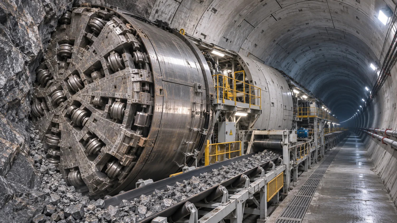
How TBM Excavation Works in Rock and Soft Ground: A Practical Guide
TBM Excavation in rock and soft ground explained: compare machine types, ground support, spoil removal, and the factors that guide smarter project planning.
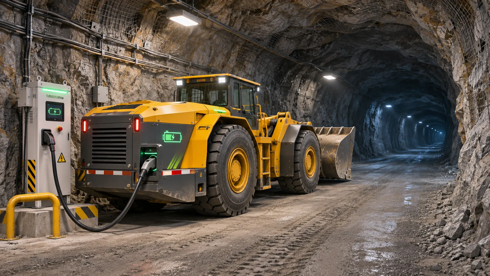
Choosing a Zero-Emission Underground Equipment Supplier: What to Check
Choosing a zero emission underground equipment supplier? Compare duty-cycle performance, charging, safety, total costs and support before you commit.
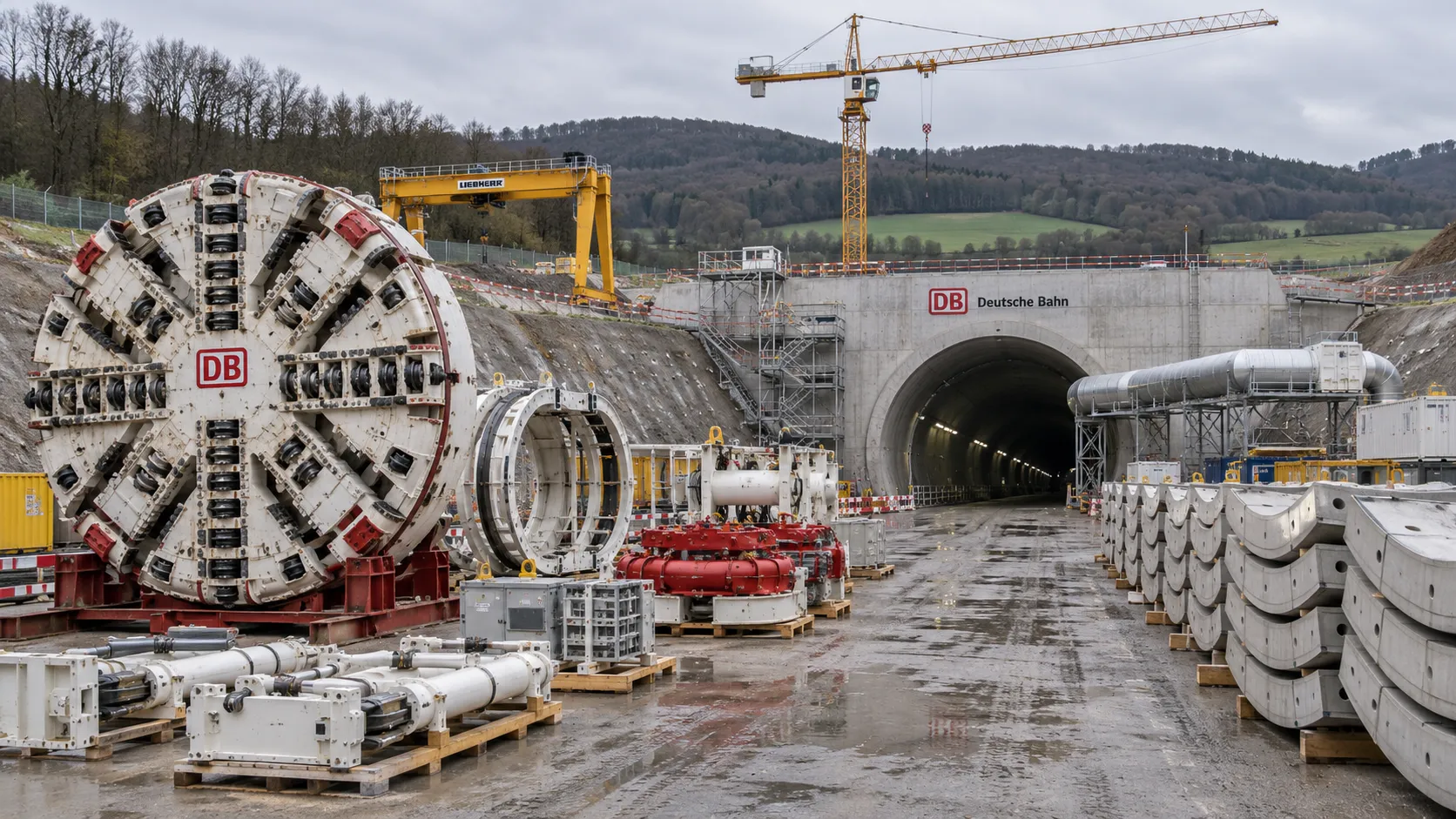
Construction Starts on Germany's Pfaffensteig Rail Tunnel, With Two TBMs Planned
Pfaffensteig rail tunnel construction is underway in Germany. Discover how two planned TBMs will support the 11-kilometre project near Stuttgart.
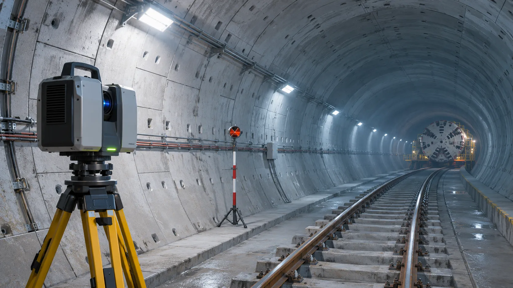
How Real-Time Underground Mapping Systems Work in Tunneling
Discover how real-time underground mapping systems guide tunneling teams, integrate sensor data, and support confident decisions with verified accuracy.
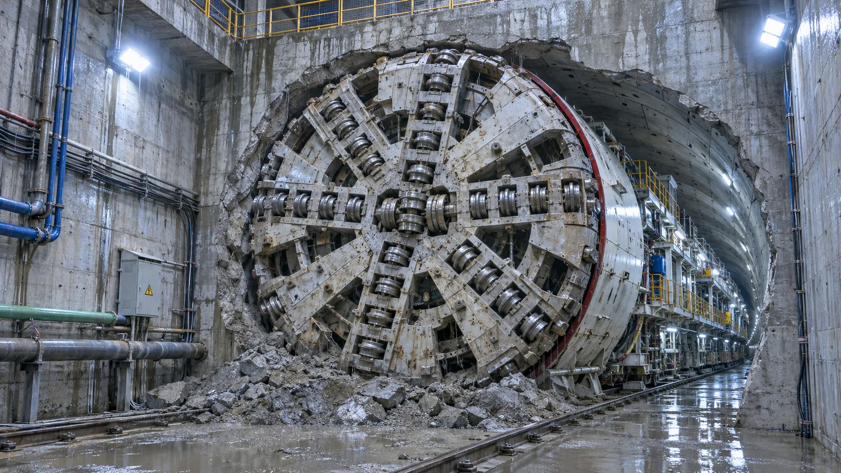
First Mechanized Tunnel Crossing Beneath the Panama Canal Completed
Panama Canal tunnel crossing: Explore the reported Metro Line 3 milestone and what it could mean for future underwater tunneling projects.
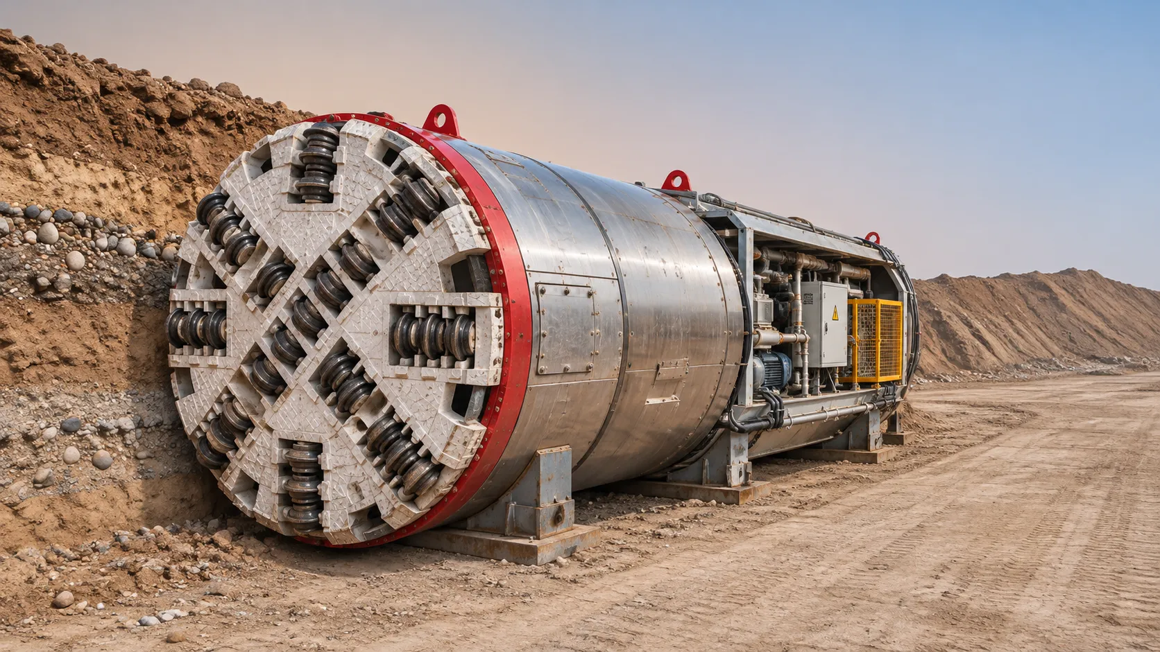
Underground Utility Construction Equipment: Choosing by Ground Conditions
Choose underground utility construction equipment with confidence. Compare trenching, HDD, microtunnelling and TBMs by ground conditions, risk and cost.
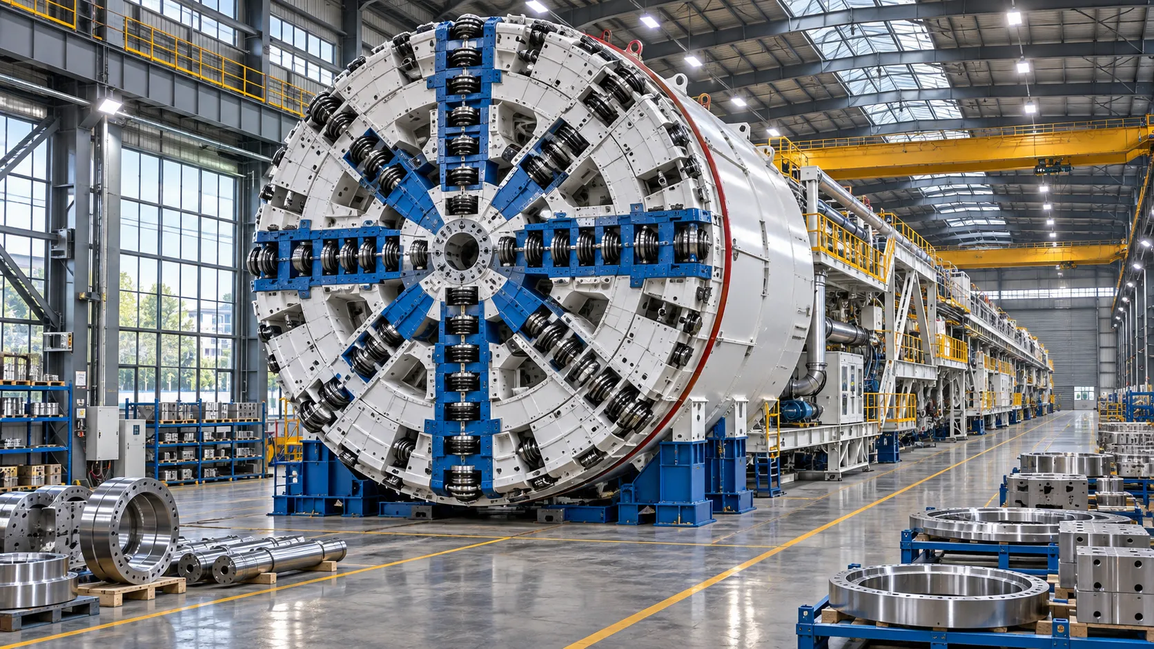
China Sets Tunnel Boring Machine Export Controls as India Pushes Local Production
China tunnel boring machine export controls could reshape procurement as India pushes local production. Explore potential supply and project impacts.
Choosing a Trenchless Pipeline Installation Contractor: Key Qualifications
Choose a trenchless pipeline installation contractor with confidence. Learn how to assess experience, equipment, safety, costs, and project risks before you hire.
China's 70% TBM Share and Export Controls Challenge India's Local Production
China's TBM export controls could challenge India's local production and infrastructure sourcing. Explore the potential risks and procurement options.
Related News
- 00
0000-00
How TBM Excavation Works in Rock and Soft Ground: A Practical Guide - 00
0000-00
Choosing a Zero-Emission Underground Equipment Supplier: What to Check - 00
0000-00
Construction Starts on Germany's Pfaffensteig Rail Tunnel, With Two TBMs Planned - 00
0000-00
How Real-Time Underground Mapping Systems Work in Tunneling - 00
0000-00
First Mechanized Tunnel Crossing Beneath the Panama Canal Completed
Weekly Insights
Stay ahead with our curated technology reports delivered every Monday.