Which Trenchless Construction Technique Fits Your Utility Crossing Conditions?





Which Trenchless Construction Technique Fits Your Utility Crossing Conditions?
Selecting among trenchless construction techniques is not a matter of choosing the most familiar machine or the lowest initial bid. A utility crossing beneath a highway, railway, river, active industrial site, or congested urban corridor is governed by physical constraints that do not negotiate: geology, groundwater, cover, pipe geometry, launch and reception space, and the consequences of losing line or grade.
Horizontal directional drilling (HDD), auger boring, guided boring, microtunnelling, and pipe jacking can all create crossings with limited surface disruption. Yet they do not manage risk in the same way. A method that works well for a long, curved pressure main in competent soils may be a poor choice for a short gravity sewer requiring tight grade control. The most useful early question is therefore not “Which method is best?” but “Which uncertainty can this method tolerate on this crossing?”
For project managers, that distinction affects permits, temporary works, contractor capability, utility protection plans, schedule contingency, and the final operational reliability of the installed asset. The decision should be made from verified site information rather than an assumed ground profile or a generic equipment preference.
Start With the Crossing Envelope, Not the Equipment
Before comparing methods, define the crossing envelope: the allowable route between entry and exit points, the required pipe material and diameter, the minimum cover, the acceptable tolerance in line and grade, and the surface assets that cannot be disturbed. This turns a broad construction question into an engineering decision.
A pressurized water main, gas line, cable duct bank, and gravity sewer may occupy similar corridors but impose very different demands. Pressure pipelines can often accept a degree of vertical or horizontal curvature if the product pipe and fittings allow it. Gravity systems generally cannot. Their long-term performance depends on maintaining design gradient, which brings active guidance and continuous steering accuracy much closer to the center of the method-selection process.
The ground investigation must also answer more than whether the site is “soil” or “rock.” Relevant questions include the likely presence of cobbles, boulders, fill, abrasive sands, soft clay, fractured rock, mixed-face conditions, voids, and variable groundwater pressure. A borehole log is valuable, but its spacing and position may not fully represent the planned drive. Where uncertainty remains, the selection should include a practical response plan for obstructions, drilling-fluid losses, face instability, or excessive jacking loads.
Where HDD Is Usually Strong—and Where It Demands Caution
HDD is often the first technique considered for utility crossings because it can complete long installations from relatively compact work areas and can follow curved alignments. The process typically involves a pilot bore, progressive reaming, and pullback of the product pipe. It is particularly relevant where the route must pass beneath roads, waterways, landscaped areas, or developed land without opening a continuous trench.
It is generally most attractive when the installed pipe can be pulled, the alignment has enough room for drill-string curvature, and the geological conditions can support a stable borehole with manageable drilling-fluid behavior. HDD is commonly considered for pressure pipes, conduits, and cable installations. Its flexibility can be a major benefit when entry and exit locations are constrained.
That flexibility should not be confused with unlimited control. HDD is less naturally suited to crossings where a gravity pipeline requires highly precise line and grade over the full drive. It also becomes more complex in coarse, loose formations, very shallow cover, highly fractured ground, or formations where drilling fluid may escape into sensitive surroundings. An inadvertent return is not simply a fluid-management inconvenience; under a watercourse, transport route, or environmentally constrained area, it can interrupt the project and alter the risk profile substantially.
For HDD, the design review should examine allowable bend radius, pull forces, bore stability, fluid volumes and containment, annular-space requirements, crossing depth, and the feasibility of locating and steering along the intended path. If the pipe coating, joints, or tensile capacity impose limits, those constraints need to be resolved before the contractor mobilizes.
Microtunnelling and Pipe Jacking: When Accuracy Drives the Decision
Microtunnelling and pipe jacking are often better aligned with projects where installed line and grade are non-negotiable. A remotely controlled, guided microtunnelling machine excavates at the face while prefabricated pipes are pushed from a launch shaft. Spoil removal and face-support arrangements vary with machine configuration and ground conditions, but the central project advantage is controlled guidance rather than simple directional reach.
This makes the method especially relevant for gravity sewers, drainage works, crossings beneath railways, and urban corridors where settlement control and positional certainty carry a high value. Pipe jacking can also be applied to larger utility tunnels and casings, although shaft construction, pipe-joint design, lubrication, and thrust capacity become increasingly significant as diameter and drive length rise.
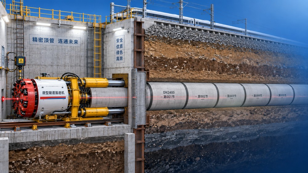
The trade-off is that the method needs launch and reception shafts or suitable pits. Those works can dominate the construction footprint, utility-diversion effort, dewatering strategy, and local permitting requirements. A technically elegant drive is not automatically the lowest-risk solution if the launch shaft sits beside sensitive foundations, in contaminated ground, or within a heavily congested utility zone.
Groundwater requires particular attention. Depending on the chosen machine and geology, face pressure, slurry handling, and separation capacity may be essential to maintain stability and reduce settlement risk. In difficult or variable soils, it is wise to assess the full system: machine, guidance, jacking frame, pipe string, lubrication approach, spoil circuit, slurry treatment where applicable, and emergency access. Evaluating only the cutting head leaves important failure modes unaddressed.
Auger Boring and Guided Boring for More Defined Crossings
Auger boring remains a practical option for relatively straight crossings where a casing is required, often beneath roads or rail corridors. The casing is advanced from a jacking pit while augers remove excavated material. It can be an efficient approach when surface access permits pits at both ends and the alignment does not demand curves.
Its limitations are equally important. Conventional auger boring does not offer the same active steering capability as microtunnelling, and difficult ground can affect control and productivity. Boulders, unstable material, groundwater, or long drives may require a different technique, more specialized tooling, or a revised installation concept. Where grade tolerance is strict, guided boring systems may offer a more suitable level of control for smaller-diameter work, provided the specific application and local ground conditions fit their operating range.
The Conditions That Commonly Change a Preliminary Choice
Several conditions routinely overturn an early method preference. The first is mixed geology. A route moving from soft soil into weathered rock, then into competent rock, may challenge cutting tools, steering, and spoil transport differently along the same crossing. The second is insufficient cover. Reduced separation from the surface or from existing utilities narrows the margin for ground movement, fluid loss, and deviation.
Third is restricted shaft or rig access. A method can appear ideal on a plan drawing but become impractical when crane access, traffic staging, spoil storage, drilling-fluid handling, noise limits, or adjacent utility clearances are examined. Fourth is the distinction between a carrier pipe and a product pipe. Installing a steel casing with a later carrier-pipe insertion is a different engineering problem from directly installing the final pipe, particularly when corrosion protection, spacers, grouting, future inspection, or thermal movement are relevant.
Do not leave the receiving end until late in planning. A reception pit may need less space than a launch shaft, but it still has to accommodate breakthrough, retrieval, lifting, water control, and safe access. For HDD, the pullback side requires adequate pipe-stringing area and an installation sequence that protects the product pipe. For pipe jacking, the reception arrangement must allow controlled machine recovery and completion of the final connection.
Build the Selection Around Consequence, Not Just Cost
A lower quoted construction cost can be misleading when it assumes favorable ground, simplified traffic control, or minimal contingency for difficult conditions. The useful comparison is total project exposure: direct construction cost, shaft and site works, temporary land requirements, schedule sensitivity, restoration, third-party approvals, environmental controls, and the cost of a failed or abandoned bore.
For a crossing beneath critical rail infrastructure or a high-consequence roadway, predictable alignment and conservative settlement control may justify a method with greater setup effort. In a lower-consequence open corridor, a less elaborate method may be entirely appropriate. The answer is not automatically “more technology.” It is a technique whose controllability matches the consequence of deviation or ground loss.
Procurement documents should ask contractors to state their assumptions, rather than merely provide a method name. Useful submissions identify anticipated ground response, tooling concept, guidance method, fluid or spoil-management plan, allowable jacking or pull forces, proposed monitoring, intervention measures, and similar-project experience relevant to the actual conditions. This makes competing proposals easier to compare and exposes gaps before they become claims or delays.
A Practical Review Before Committing
A sound decision meeting should bring the designer, geotechnical team, utility owner, construction representative, and asset operator around the same set of project facts. Confirm the horizontal and vertical alignment, ground investigation coverage, existing-service records, pipe properties, hydraulic or operational requirements, access constraints, groundwater observations, and approval conditions. Then test each candidate method against the issues most likely to stop it.
At UTMD, trenchless engineering is viewed within the wider discipline of underground construction: cutting mechanics, machine guidance, face behavior, material transport, and equipment reliability all interact. The same systems thinking used to examine full-face TBMs and pipe jacking machines is useful at utility-crossing scale. A machine is only one part of a controlled installation; site logistics, sensing, operator decisions, and ground response determine whether the crossing remains predictable.
The final choice should be documented as a set of conditions, not a slogan: this technique is preferred because it meets the required accuracy, works within the available footprint, suits the interpreted ground, and has a credible response to the identified risks. If those conditions change after further investigation, the selected trenchless construction technique should be revisited before construction starts. That discipline protects more than the crossing itself—it protects the project schedule, the surrounding infrastructure, and the operating asset that will remain underground long after the worksite has disappeared.
Related News
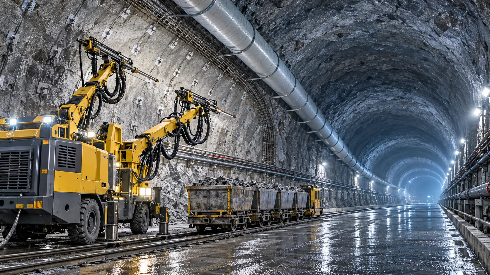
How to Evaluate European Drill-and-Blast Tunnelling Contractors for Complex Projects
Drill and blast tunnelling contractors Europe: learn how to assess geology expertise, blast control, equipment reliability, safety, and programme resilience for complex projects.
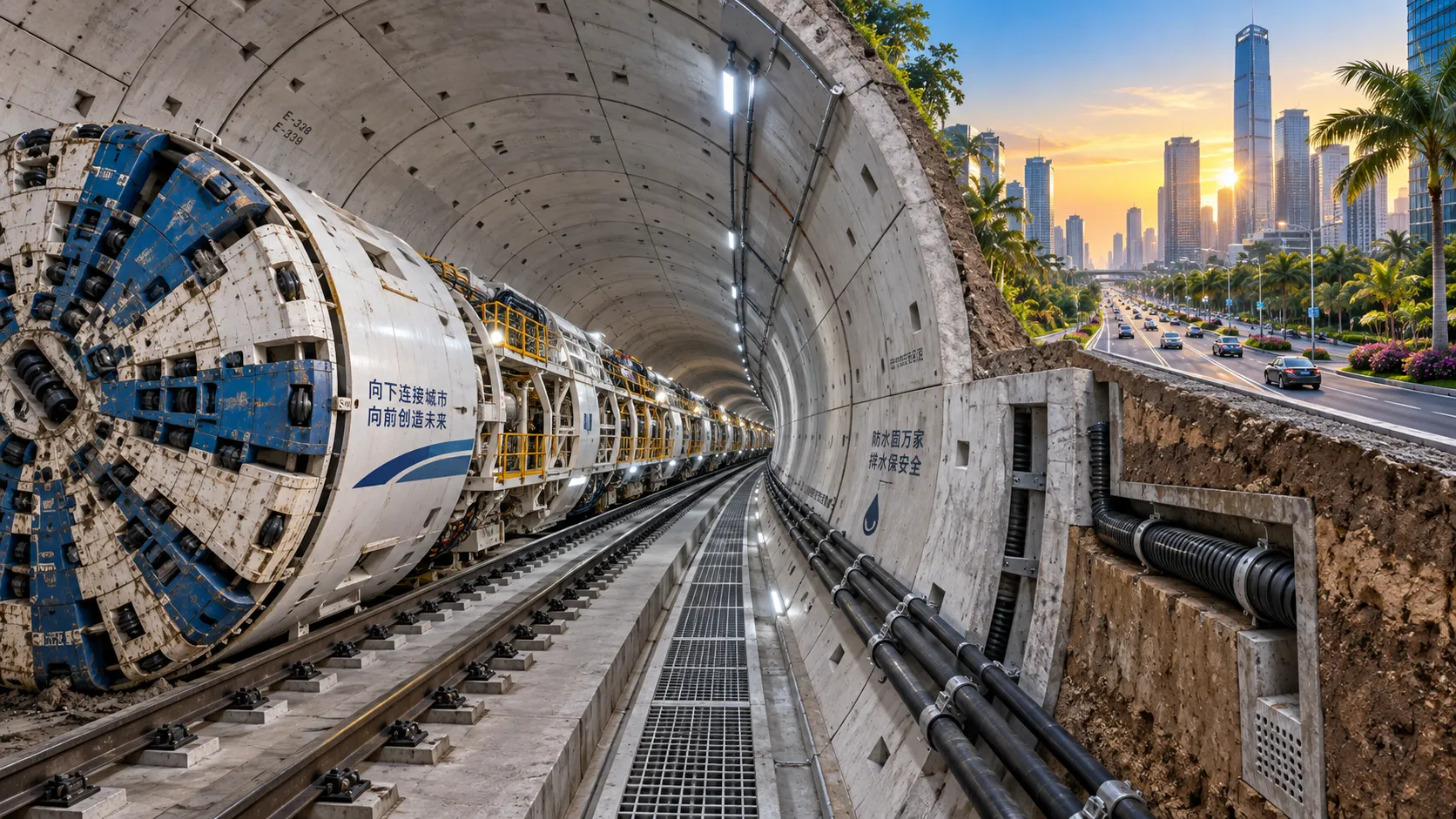
What Is Driving Metro Tunnelling Demand Across Southeast Asia’s Major Cities?
Metro tunnelling Southeast Asia is accelerating as major cities tackle congestion, flooding, and connectivity. Explore the market forces, technical risks, and opportunities shaping demand.
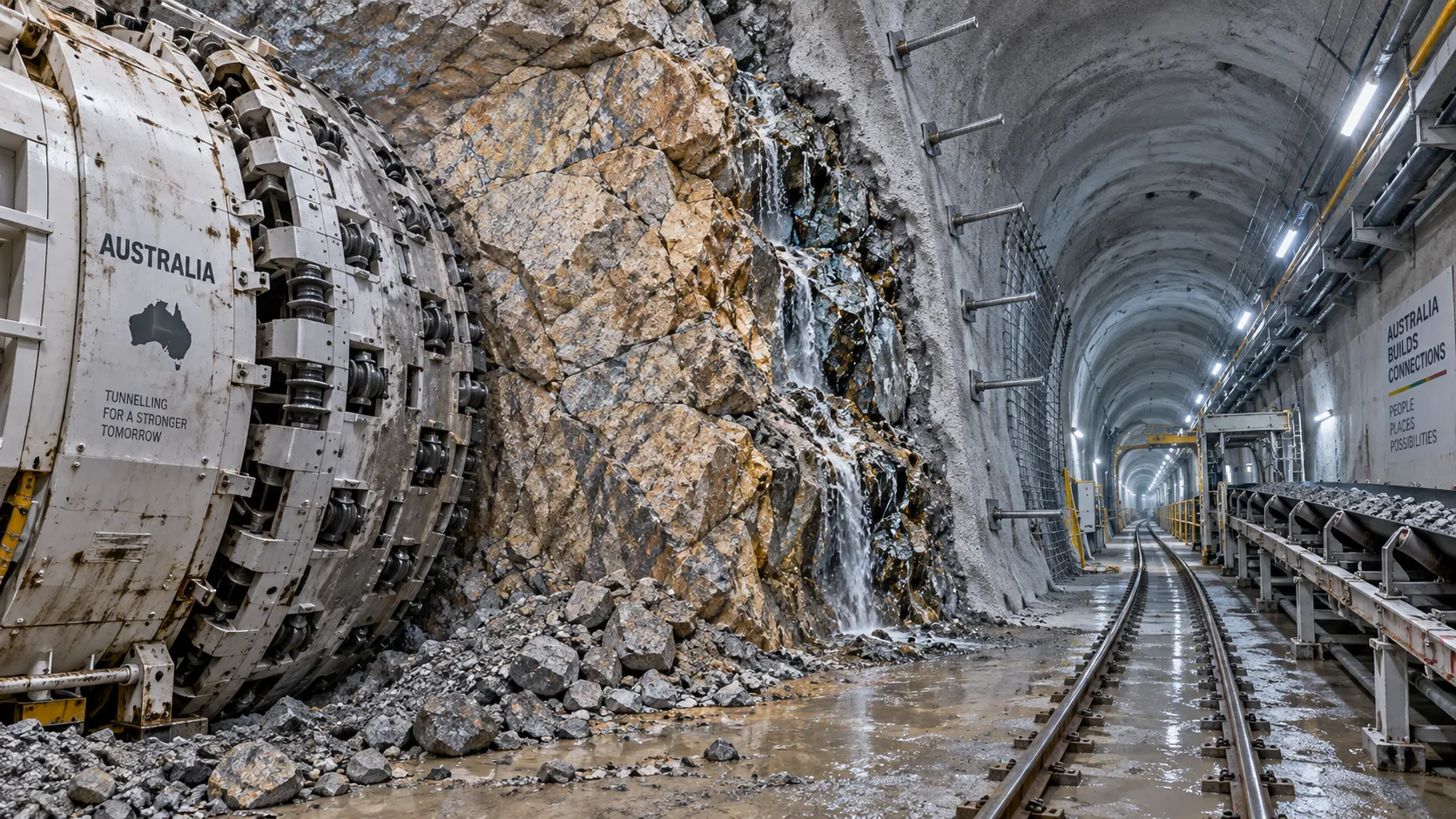
Hard Rock Tunnelling in Australia: Selecting Methods for Variable Ground Conditions
Hard rock tunnelling in Australia: compare TBM, drill-and-blast and hybrid methods to manage variable ground, reduce risk and protect project costs.
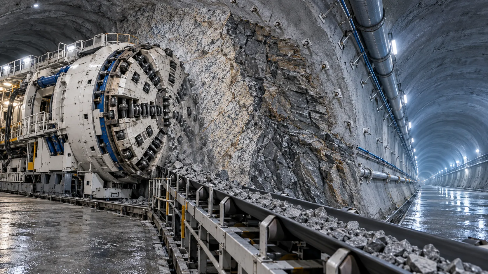
Hydropower Tunnel Excavation: Selecting Methods for Variable Rock Conditions
Hydropower tunnel excavation methods for variable rock conditions: compare TBM, drill-and-blast, and hybrid strategies to improve safety, progress, and project control.
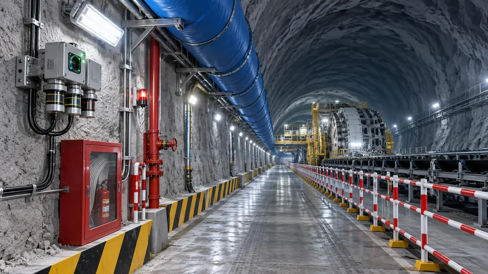
How to Select Underground Safety Equipment for Tunnelling by Hazard and Work Zone
Underground Safety Equipment for tunnelling: match protection to hazards, work zones, compliance, and emergency needs with this practical selection guide.
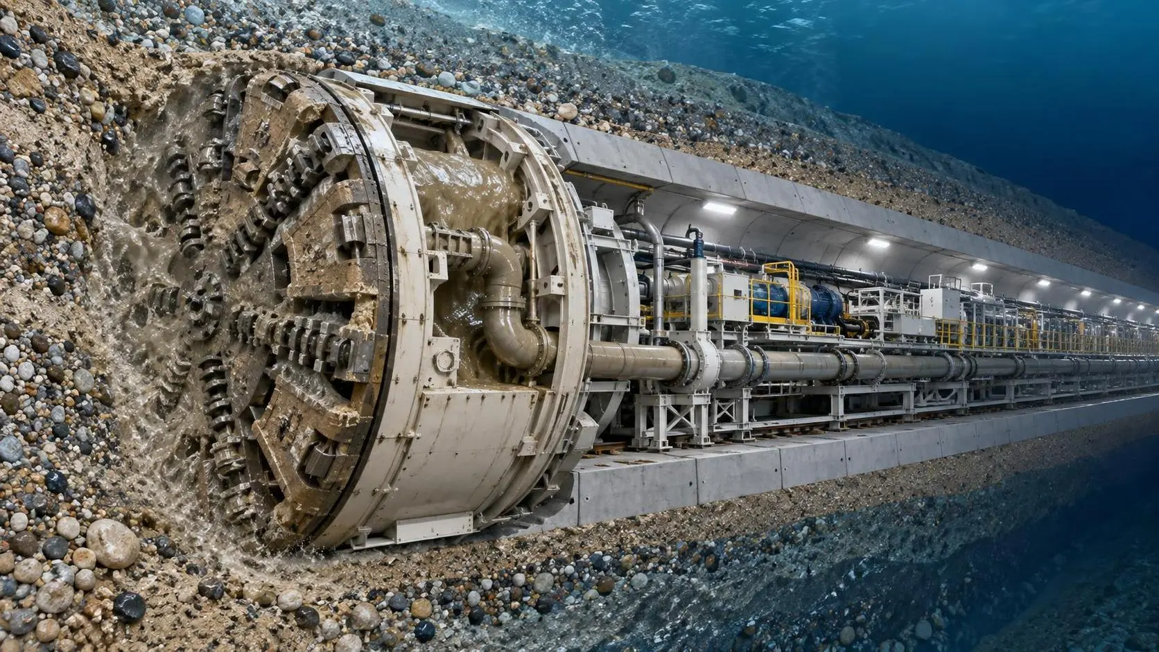
EPB or Slurry Shield? Selecting Soft-Ground Tunnelling Equipment by Soil Conditions
Tunnel Excavation Equipment for soft ground: compare EPB and slurry shields by soil, groundwater, settlement risk, and project logistics to choose confidently.
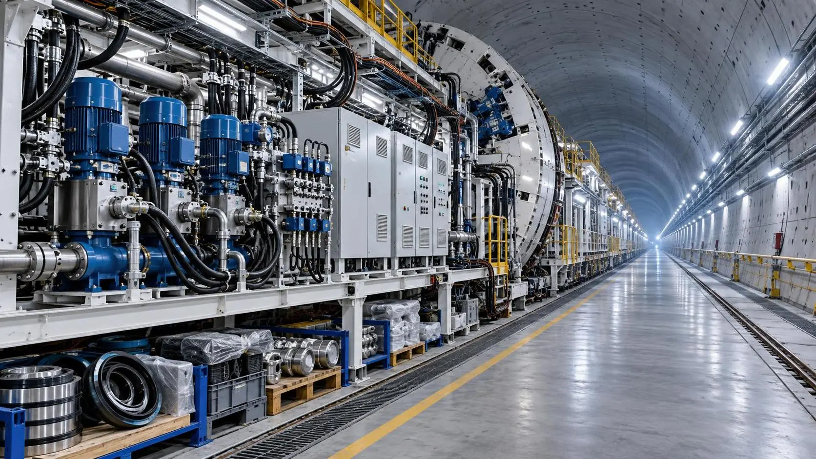
How to Specify TBM Backup System Parts for Reliable Long-Distance Tunnelling
TBM backup system parts: learn how to specify reliable spares for long-distance tunnelling, reduce downtime, ensure compatibility, and speed underground recovery.
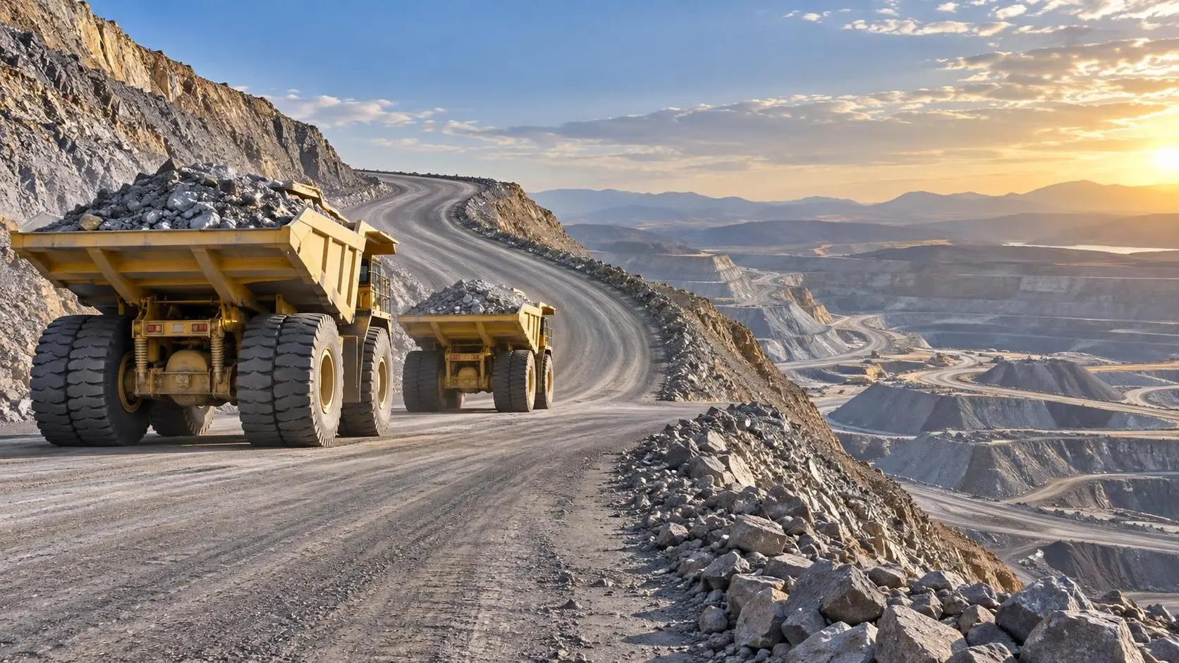
How to Size Open Pit Mining Trucks for Haul Distance, Grade, and Payload?
Open Pit Mining Trucks: learn how to match payload, haul distance, grade, road resistance, and loading capacity for safer, lower-cost mine operations.
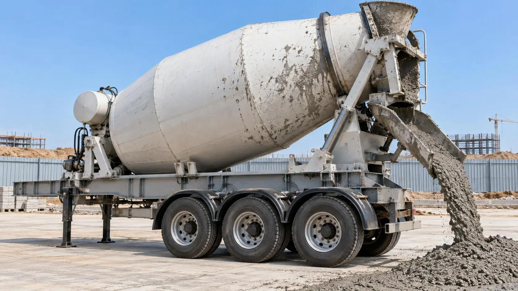
Evaluating Structural Durability and Maintenance Frequency in Heavy-Duty Concrete Mixer Trailers Under Frequent Dump Cycles
Discover how dump special trailers withstand 12–18 daily dump cycles — structural durability, maintenance optimization & real-world fleet insights revealed.
Related News
- 00
0000-00
How to Evaluate European Drill-and-Blast Tunnelling Contractors for Complex Projects - 00
0000-00
Which Trenchless Construction Technique Fits Your Utility Crossing Conditions? - 00
0000-00
What Is Driving Metro Tunnelling Demand Across Southeast Asia’s Major Cities? - 00
0000-00
Hard Rock Tunnelling in Australia: Selecting Methods for Variable Ground Conditions - 00
0000-00
Hydropower Tunnel Excavation: Selecting Methods for Variable Rock Conditions
Weekly Insights
Stay ahead with our curated technology reports delivered every Monday.