
Microtunneling Pipe Installation: Planning Shafts and Managing Jacking Loads





Microtunneling Pipe Installation: Planning Shafts and Managing Jacking Loads
Microtunneling pipe installation can protect busy streets from extensive excavation, but project success depends on decisions made before the first pipe enters the ground. Launch and reception shaft layouts, groundwater control, and allowable jacking loads are closely linked—not separate design tasks. Underestimating these interfaces can leave a drive stalled beneath a road, with limited options for recovery.
The practical challenge is to create a system that remains workable when conditions differ from the baseline. That means checking more than machine thrust and nominal pipe strength. Shaft reactions, joint geometry, lubrication delivery, steering corrections, and restart loads all influence whether the planned drive can actually be completed.
Fix the alignment and ground assumptions before shrinking the shafts
On constrained urban sites, shaft footprints often become a negotiation between utilities, traffic management, property boundaries, and available work areas. The temptation is to agree the smallest footprint first and ask the tunnelling contractor to make it work. That reverses the engineering sequence.
Start with the alignment, cover, pipe dimensions, machine configuration, and anticipated ground behaviour. Investigations should address conditions along the drive as well as at the shafts. A borehole beside the launch location cannot establish whether the machine will encounter an abrasive layer, a permeable lens, or an obstruction halfway across the alignment.
Groundwater deserves particular attention. Establish the expected pressure at tunnel level, potential seasonal variation, and whether nearby foundations or utilities are sensitive to drawdown. These findings affect face-support requirements, shaft construction, launch and reception seals, and the consequences of an uncontrolled hydraulic connection.
For a gravity sewer, also confirm the tolerance budget before construction. Survey accuracy, shaft position, machine guidance, steering capability, and joint deflection must collectively support the required line and grade. An alignment that is geometrically possible may still be impractical within the available correction limits.
Design the launch shaft around the complete operating cycle
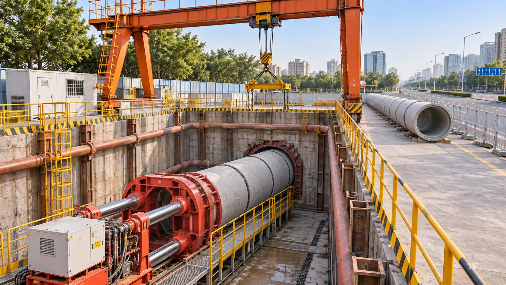
A launch shaft must accommodate more than the microtunnel boring machine and jacking frame. Its usable internal dimensions must allow pipe lowering, joint preparation, thrust-ring installation, service connections, surveying, inspection, and safe access. Check clearances against the actual equipment arrangement, not a generic shaft sketch.
Pipe length is a consequential choice. Shorter pipes may reduce the required shaft length, but they introduce more joints and more connection cycles over the drive. Longer pipes reduce those cycles but increase lifting and handling demands. Neither option is automatically cheaper once shaft construction and operating time are considered together.
The thrust reaction needs an explicit load path from the jacking frame into the reaction structure, shaft support, and surrounding ground. The temporary works designer should check the relevant operating cases, including eccentric loading where applicable. A frame with ample hydraulic capacity is of little use if its reaction arrangement cannot safely accept the force.
Surface logistics can quietly control progress. Slurry separation equipment, lubrication tanks, lifting positions, pipe storage, and delivery vehicles compete for space. Check the lift plan and service routes against the shaft arrangement. A layout that requires repeated equipment relocation between pipe deliveries creates interruptions that the tunnelling programme may not contain.
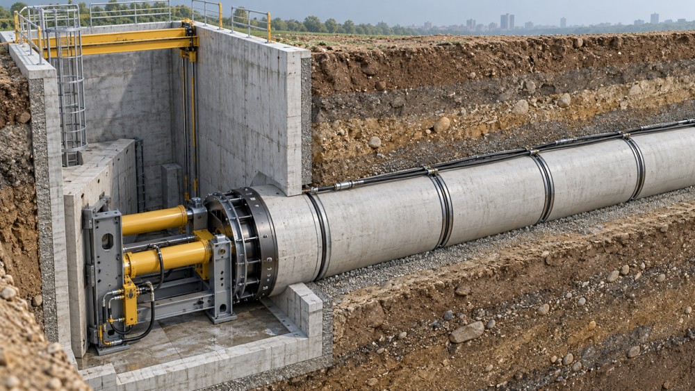
Reception is a designed operation, not simply the end of the drive
The reception shaft needs sufficient space for breakthrough control, machine recovery, lifting equipment, and any dismantling required. Allow for the machine’s arrival position within the accepted alignment tolerance, rather than assuming it will reach the exact centre of the opening.
Where groundwater or unstable ground is present, define the reception seal and any treatment zone before launch. The transition from supported excavation into the shaft can create a pathway for water and soil loss. Breakthrough sequencing, pressure management, and emergency measures belong in the method statement—not in an improvised discussion as the cutterhead approaches.
Build a jacking-load envelope, not a single prediction
A useful preliminary model separates excavation-related resistance from friction along the pipe string. Pipe diameter, drive length, ground behaviour, overcut, lubrication, alignment, and stoppages all influence the result. Friction assumptions are particularly uncertain because the annulus does not necessarily remain uniform or continuously lubricated.
Ask for expected operating loads alongside credible adverse cases: reduced lubrication effectiveness, a planned stoppage, restart after an extended interruption, and steering through a difficult section. The purpose is not to predict every event precisely. It is to expose which assumptions consume the available capacity.
The governing allowable thrust is the lowest relevant limit across the system. That includes the pipe and joint assembly under actual loading conditions, the jacking equipment, thrust-transfer components, and shaft reaction works. Ultimate or test capacities must not be treated as interchangeable with permissible construction loads.
Joint behaviour is often decisive. Angular deflection and eccentric contact can produce local stresses well above those implied by average axial compression. Confirm the pipe supplier’s allowable jacking loads, packer requirements, and joint-deflection limits for the proposed arrangement. Curves and frequent steering corrections need particular scrutiny.
There is therefore no universal maximum drive length for a given pipe diameter. A longer, straight drive through consistent ground with effective lubrication may be more manageable than a shorter drive with changing ground, poor annular support, and repeated corrections. Drive length is an outcome of the system assessment, not a standalone equipment claim.
Treat lubrication as an engineered delivery system
Specifying bentonite lubrication is not enough. The plan should establish injection-point locations, distribution along the string, mixing and storage arrangements, pumping capability, and how injection pressure and volume will be recorded. Material selection should account for groundwater chemistry and ground permeability.
In permeable ground, lubricant may escape into the formation instead of maintaining an effective annular layer. Elsewhere, changing ground conditions or interruptions may make friction less predictable. A rising thrust trend should prompt a review of delivery records and ground behaviour—not an automatic increase in pressure.
Injection pressure must remain compatible with cover, groundwater conditions, nearby assets, and the risk of ground disturbance or fluid escape. Excess pressure is not a reliable cure for inadequate distribution. Confirm that the intended injection points are functioning before changing the operating regime.
Stoppages also need planning. A weekend shutdown, separation-plant failure, or delayed pipe delivery may change restart behaviour. Define what lubrication, circulation, monitoring, or other measures are required during an interruption, subject to the machine design and approved method.
Decide on intermediate jacking stations while options remain open
Intermediate jacking stations divide the pipe string into sections that can be advanced in sequence. They help manage force transmission along long or demanding drives, but they do not remove ground resistance. Their effectiveness depends on location, operating sequence, available stroke, and compatible pipe and station design.
Assess the need before mobilisation, including installation positions and hydraulic services. Retrofitting a station after loads approach the permissible limit may be impractical. Conversely, installing stations without a clear operating need adds cost, connections, and commissioning work.
A sensible decision compares the adverse load envelope with permissible section loads and the consequences of losing lubrication effectiveness. Include station closure, sealing, and final pipeline requirements in that decision. Temporary jacking hardware must not leave unresolved constraints for the completed asset.
Use trends to intervene before capacity is exhausted
Monitoring becomes useful when measurements lead to agreed actions. Record jacking thrust against chainage and relate it to advance rate, cutterhead torque, face or slurry pressures, lubrication records, steering activity, and stoppages. Synchronised records make it easier to distinguish increasing pipe friction from a changing excavation condition.
For example, rising thrust with relatively stable cutting behaviour suggests a different investigation from simultaneous changes in thrust, torque, and slurry performance. Neither pattern proves a diagnosis on its own. It does, however, help the team choose a targeted check instead of changing several settings at once.
- Set warning and hold points: tie them to approved system limits, leaving room to investigate before reaching the permissible maximum.
- Assign decision authority: identify who can stop jacking, authorise restart, and approve changes to operating parameters.
- Define event reviews: require reassessment after unusual ground response, significant alignment correction, prolonged stoppage, or unexplained thrust growth.
Settlement and asset monitoring should sit alongside machine records. Acceptable thrust does not demonstrate acceptable ground behaviour. Face-support problems or soil loss can develop without a dramatic jacking-load warning.
Close the interfaces before authorising launch
Before launch, bring the shaft designer, tunnelling contractor, pipe supplier, geotechnical adviser, and monitoring team into one review. Resolve discrepancies between equipment capacity, permissible pipe loads, shaft reactions, and operating thresholds. Separate approvals are insufficient if each party has assumed a different maximum thrust.
UTMD’s underground-engineering coverage connects equipment capability with project delivery constraints. For microtunneling pipe installation, that connection is practical: a capable machine cannot compensate for an undersized reaction system, inaccessible lubrication connections, or an unplanned reception operation.
The launch decision should rest on a coordinated load envelope, buildable shaft arrangements, and a credible response to rising resistance. If the drive depends on uninterrupted progress and consistently ideal friction, revisit the plan while changing it is still possible from the surface.
Related News
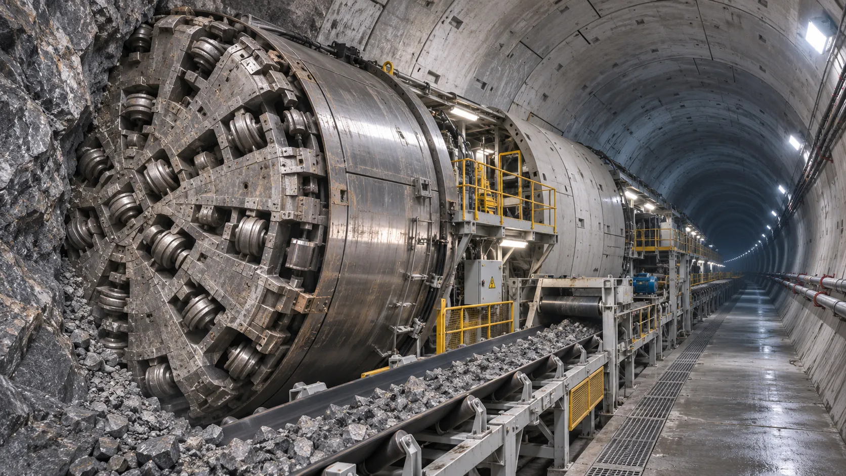
How TBM Excavation Works in Rock and Soft Ground: A Practical Guide
TBM Excavation in rock and soft ground explained: compare machine types, ground support, spoil removal, and the factors that guide smarter project planning.
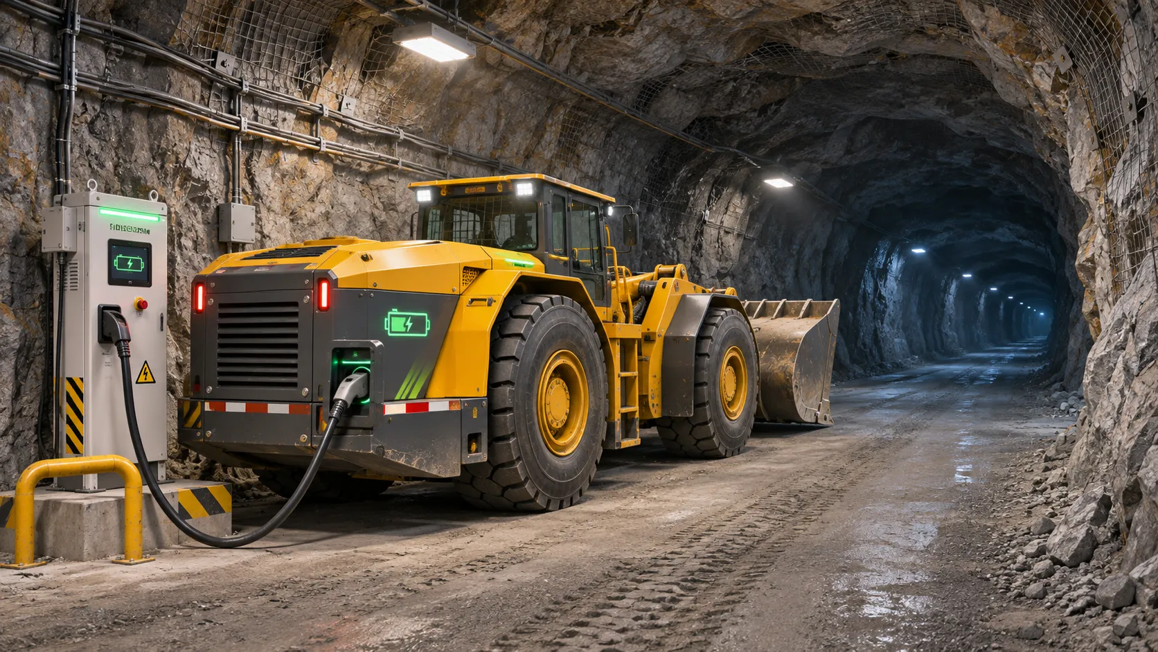
Choosing a Zero-Emission Underground Equipment Supplier: What to Check
Choosing a zero emission underground equipment supplier? Compare duty-cycle performance, charging, safety, total costs and support before you commit.
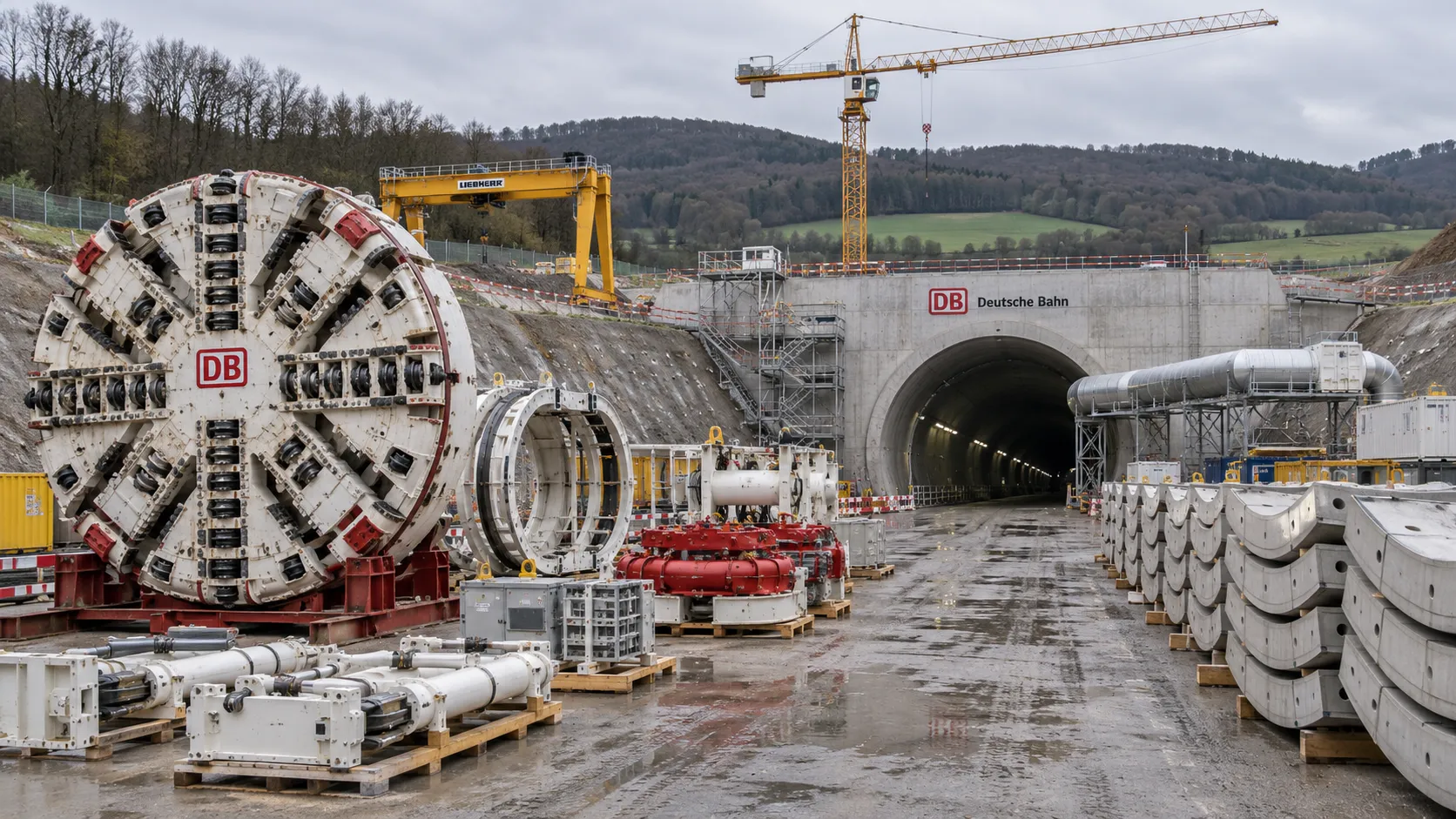
Construction Starts on Germany's Pfaffensteig Rail Tunnel, With Two TBMs Planned
Pfaffensteig rail tunnel construction is underway in Germany. Discover how two planned TBMs will support the 11-kilometre project near Stuttgart.
How Real-Time Underground Mapping Systems Work in Tunneling
Discover how real-time underground mapping systems guide tunneling teams, integrate sensor data, and support confident decisions with verified accuracy.
First Mechanized Tunnel Crossing Beneath the Panama Canal Completed
Panama Canal tunnel crossing: Explore the reported Metro Line 3 milestone and what it could mean for future underwater tunneling projects.
Underground Utility Construction Equipment: Choosing by Ground Conditions
Choose underground utility construction equipment with confidence. Compare trenching, HDD, microtunnelling and TBMs by ground conditions, risk and cost.
China Sets Tunnel Boring Machine Export Controls as India Pushes Local Production
China tunnel boring machine export controls could reshape procurement as India pushes local production. Explore potential supply and project impacts.
Choosing a Trenchless Pipeline Installation Contractor: Key Qualifications
Choose a trenchless pipeline installation contractor with confidence. Learn how to assess experience, equipment, safety, costs, and project risks before you hire.
China's 70% TBM Share and Export Controls Challenge India's Local Production
China's TBM export controls could challenge India's local production and infrastructure sourcing. Explore the potential risks and procurement options.
Related News
- 00
0000-00
How TBM Excavation Works in Rock and Soft Ground: A Practical Guide - 00
0000-00
Choosing a Zero-Emission Underground Equipment Supplier: What to Check - 00
0000-00
Construction Starts on Germany's Pfaffensteig Rail Tunnel, With Two TBMs Planned - 00
0000-00
How Real-Time Underground Mapping Systems Work in Tunneling - 00
0000-00
First Mechanized Tunnel Crossing Beneath the Panama Canal Completed
Weekly Insights
Stay ahead with our curated technology reports delivered every Monday.