
Selecting TBM Cutter Tools for European Mixed-Ground Tunnelling Projects





Tool selection should begin with the ground model at cutterhead scale, not with a preferred disc diameter or a catalogue wear grade. European mixed-ground drives often pass through short, irregular transitions: competent rock beside weathered seams, coarse glacial deposits over clay, weak rock softened by groundwater, or artificial fill around older utilities and foundations. A cutter package that performs well in a uniform section can become unreliable when the face contains materials requiring very different cutting, mixing, and conditioning behaviour.
For TBM cutter tools Europe projects require, the practical objective is to maintain a stable cutting process while limiting unplanned access to the cutterhead. Penetration rate matters, but it should be judged together with cutter consumption, torque variation, chamber behaviour, spoil removal, and the feasibility of changing tools under the expected pressure conditions. The selected tools must match the machine type, cutterhead layout, and intervention strategy as one system.
Start with the transition zones, not the dominant geology
A geological baseline may describe the main formations accurately while underrepresenting the interfaces that create the hardest tool decisions. Cutter damage often accelerates where hard, abrasive fragments are embedded in soft matrix material, where a faulted rock mass includes clay-rich gouge, or where a permeable layer admits water and fines into the excavation chamber. These intervals deserve separate tool assumptions even when they occupy a modest portion of the alignment.
Rock strength alone is an incomplete basis for choosing disc cutters. A strong but homogeneous formation can allow predictable rolling and stable cutter loading. A weaker formation containing angular quartz-rich gravel, chert bands, iron-rich inclusions, or boulders can generate severe localized impact and abrasive wear. Conversely, fractured rock may reduce the force needed for breakage while increasing the chance of uneven cutter contact, ring cracking, blocked rotation, and sudden load peaks.
Review the ground investigation for discontinuity spacing, weathering profile, grain hardness, cementation, cobble and boulder potential, abrasivity indicators, water-bearing layers, and anticipated face instability. The useful question is not simply whether rock is “hard” or soil is “soft.” It is whether the material will form chips, crush under compression, smear across the cutterhead, scour exposed metal, or enter the machine as discrete impact bodies.
Match the tool family to the excavation mode
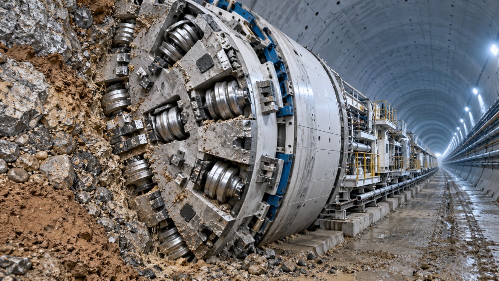
Mixed-ground machines may work with cutterheads carrying disc cutters, carbide-tipped cutting tools, scrapers, rippers, bucket lips, and wear protection in different proportions. The relative value of each item changes with the mode of excavation.
Where the cutterhead must break competent rock, disc cutters remain the primary rock-fracturing tools. Their function relies on sufficient normal force, appropriate spacing, and reliable rotation. Disc cutter selection therefore involves more than ring material. Diameter, ring profile, bearing and seal arrangement, allowable load, mounting geometry, and access direction all affect field performance.
Where soft ground, cohesive soils, or granular deposits are expected, cutting tools with carbide elements and protected bodies may dominate the excavation action. These tools need to resist abrasion and impact while preserving the cutterhead’s ability to excavate, mix, and transport material. A tool that is too aggressive in a soft cohesive face can increase clogging or disturb pressure control. A tool that is too blunt in coarse, dense material may force higher torque without producing a cleaner excavation path.
In a genuine mixed face, it is common to need both rock-breaking capacity and soil-working capability. The cutterhead arrangement should avoid treating these as separate zones with no interaction. Material released by disc cutters must still pass through the openings and chamber without accumulating around tool mounts. Fine, sticky spoil can also interfere with cutter rotation and hide early damage. Tool selection and cutterhead flow paths must be reviewed together.
Disc cutter dimensions and ring profile
Larger disc cutters generally offer greater load capacity and a broader rolling contact, which can suit competent rock and sustained high-thrust excavation. They also occupy more space, may demand heavier housings, and can be less forgiving when the face profile changes rapidly across the cutterhead. Smaller discs provide more placement flexibility, particularly near the gauge and in constrained layouts, but their loading margin and wear volume are lower.
Ring profile should reflect the expected breakage mechanism. A narrow profile concentrates force and can initiate fractures effectively in intact, hard rock, yet it is vulnerable to rapid wear in abrasive, granular conditions. A wider profile spreads the load and can better tolerate broken or heterogeneous material, though excessive width may reduce penetration efficiency in strong rock. The decision should be tied to projected contact force, cutter spacing, and expected penetration per revolution rather than chosen in isolation.
Gauge cutters need separate attention. They work near the perimeter, are exposed to side loading, and strongly influence overcut, tunnel profile, and shield clearance. In mixed ground, poor gauge tool performance may first appear as rising steering effort or local rubbing rather than an obvious drop in advance. A robust gauge arrangement often includes protection for the mounting area and a clear plan for inspecting wear before it affects machine guidance.
Wear is not a single failure mechanism
“High wear” can describe several different conditions requiring different corrective action. Uniform ring wear suggests that the tool is performing its intended work but the selected wear volume, material grade, or planned replacement interval is inadequate. Flat spots or seized cutters point toward rotation failure, bearing distress, contamination, inadequate preload, or a cutter subjected to a loading pattern outside its design envelope. Chipped carbide may indicate impact from boulders or hard inclusions, while missing carbide can result from poor retention after repeated shock and abrasion.
Tool body erosion is also distinct from cutting-edge wear. In abrasive sand, gravel, or slurry-laden spoil, the body, mounting block, fasteners, and adjacent cutterhead steel can lose material rapidly. Replacing a consumable tool does not restore a damaged mounting interface. Wear protection should be specified where flow trajectories expose these areas, with sufficient clearance so that protective elements do not trap spoil or obstruct tool replacement.
Disc cutter seal performance deserves particular scrutiny in wet, fine-grained ground. Water and abrasive fines reaching the bearing cavity can shorten service life even where the cutter ring remains serviceable. A high-quality ring cannot compensate for a seal arrangement poorly suited to the pressure, contamination, and rotational conditions at the face. Selection records should therefore distinguish ring wear, seal leakage, bearing failure, and structural damage rather than recording every removal as general cutter consumption.
Use cutterhead loading data to test the selection
Predicted thrust and torque are useful only when they are translated into local tool loads. Average machine thrust does not reveal whether a subset of face cutters will carry excessive load because of uneven geology, a worn ring, an out-of-round cutterhead path, or poor contact in a broken face. Cutter spacing, tool position, face curvature, and anticipated penetration determine the distribution of work.
During design review, compare the expected operating envelope with the rated load of each cutter position. Include transient conditions: entry into stronger bands, steering corrections, reduced penetration during conditioning changes, and torque spikes from cobbles or blocky rock. A tool selection based solely on normal steady-state conditions can leave little margin when the drive encounters the very conditions that define a mixed-ground project.
Intervention conditions change the economic threshold
The cheapest tool at purchase is rarely the lowest-cost choice when it creates a cutterhead intervention at depth or under pressure. A replacement strategy should be developed before procurement using the planned access method, exposure limits, tool-change sequence, lifting space, and likely contamination of fasteners and housings. The relevant cost comparison includes the chance that a worn or seized tool damages its holder before it can be replaced.
Front-accessible systems can reduce intervention complexity, but only if the installed tool can be released after exposure to abrasive slurry, fines, and vibration. Rear-access arrangements protect the working face of the holder differently, yet their benefit depends on actual access behind the cutterhead. For each critical tool location, confirm clearances with the installed cutterhead model rather than relying on generic assembly drawings.
Spare quantities should be split by failure mode and location. A drive through abrasive ground may consume rings and carbide tools predictably, while a boulder-prone reach needs contingency for damaged bodies, holders, and retaining components. Holding only additional cutting tips is inadequate when impact damage can affect the whole assembly. Compatibility control is equally important: similar-looking tools can have different shank dimensions, retention systems, or allowable mounting orientations.
Specify the interface, not merely the consumable
Procurement documents should define the complete installed arrangement: tool designation, material and hardfacing requirements where relevant, holder geometry, retention components, torque or locking requirements, allowable wear limits, inspection access, and traceability. Ambiguous language such as “equivalent mixed-ground cutter” invites substitutions that may fit physically but alter load capacity, wear pattern, or replacement procedure.
For disc cutters, request the information needed to evaluate service life without demanding unsupported guarantees: rated loads, ring dimensions and profile, bearing and seal design description, lubrication arrangement where applicable, permitted mounting orientation, replacement criteria, and documented dimensional interfaces. For carbide-tipped tools, examine carbide placement, protection of the transition between carbide and steel body, shank retention, and the wear path of the holder.
Installation quality has a direct effect on the apparent performance of a tool. Dirt under a mounting surface, damaged retaining hardware, incorrect locking force, or a holder distorted by earlier wear can cause vibration and premature failure. Incoming inspection should confirm that tools, holders, and retainers match the approved interface. Before commissioning, record baseline measurements at selected face and gauge locations so later wear observations are comparable.
Do not confuse cutter consumption with poor geology control
Unexpected tool loss is sometimes attributed immediately to an inaccurate ground model. That may be correct, but it is not the only explanation. A sudden rise in consumed tools can result from changed penetration practice, reduced cutter rotation due to clogging, altered conditioning, excessive steering loads, poor spoil removal, or a replacement batch with different characteristics. The investigation should compare operating records, inspection photographs, removed-tool condition, and face geology over the same chainage.
Likewise, low cutter consumption is not automatically evidence of a good selection. It can occur because penetration is too low, cutter loading is insufficient to fracture rock efficiently, or a change in operating parameters has shifted excavation work to less suitable tools. Advance, torque, thrust, chamber conditions, and wear condition need to be read together.
Build a route-specific tool strategy
A robust selection package separates baseline tools from transition-zone provisions. The baseline reflects the longest credible ground condition. Transition provisions identify which tool positions, spare assemblies, wear protections, and inspection intervals change when entering abrasive rock, coarse deposits, fault zones, or clogging-prone soils. This avoids overbuilding the entire cutterhead for a short adverse reach while ensuring that the difficult interval is not handled as an improvised exception.
Before final release, conduct a joint review of geological interpretation, cutterhead drawings, predicted machine loads, access constraints, conditioning assumptions, and replacement logistics. The output should be an operating document as well as a procurement specification: it should state what wear signatures trigger action, which parts must be available at the heading, and when a tool problem requires adjustment of excavation parameters rather than immediate replacement.
For European mixed-ground tunnelling, the most dependable cutter selection is therefore one that remains defensible when the face changes unexpectedly. It combines appropriate rock-breaking capacity, abrasion resistance, protected mounting interfaces, and a realistic intervention plan, with enough recorded evidence to distinguish normal wear from a developing cutterhead problem.
Related News

How TBM Excavation Works in Rock and Soft Ground: A Practical Guide
TBM Excavation in rock and soft ground explained: compare machine types, ground support, spoil removal, and the factors that guide smarter project planning.
Choosing a Zero-Emission Underground Equipment Supplier: What to Check
Choosing a zero emission underground equipment supplier? Compare duty-cycle performance, charging, safety, total costs and support before you commit.
Construction Starts on Germany's Pfaffensteig Rail Tunnel, With Two TBMs Planned
Pfaffensteig rail tunnel construction is underway in Germany. Discover how two planned TBMs will support the 11-kilometre project near Stuttgart.

How Real-Time Underground Mapping Systems Work in Tunneling
Discover how real-time underground mapping systems guide tunneling teams, integrate sensor data, and support confident decisions with verified accuracy.
First Mechanized Tunnel Crossing Beneath the Panama Canal Completed
Panama Canal tunnel crossing: Explore the reported Metro Line 3 milestone and what it could mean for future underwater tunneling projects.
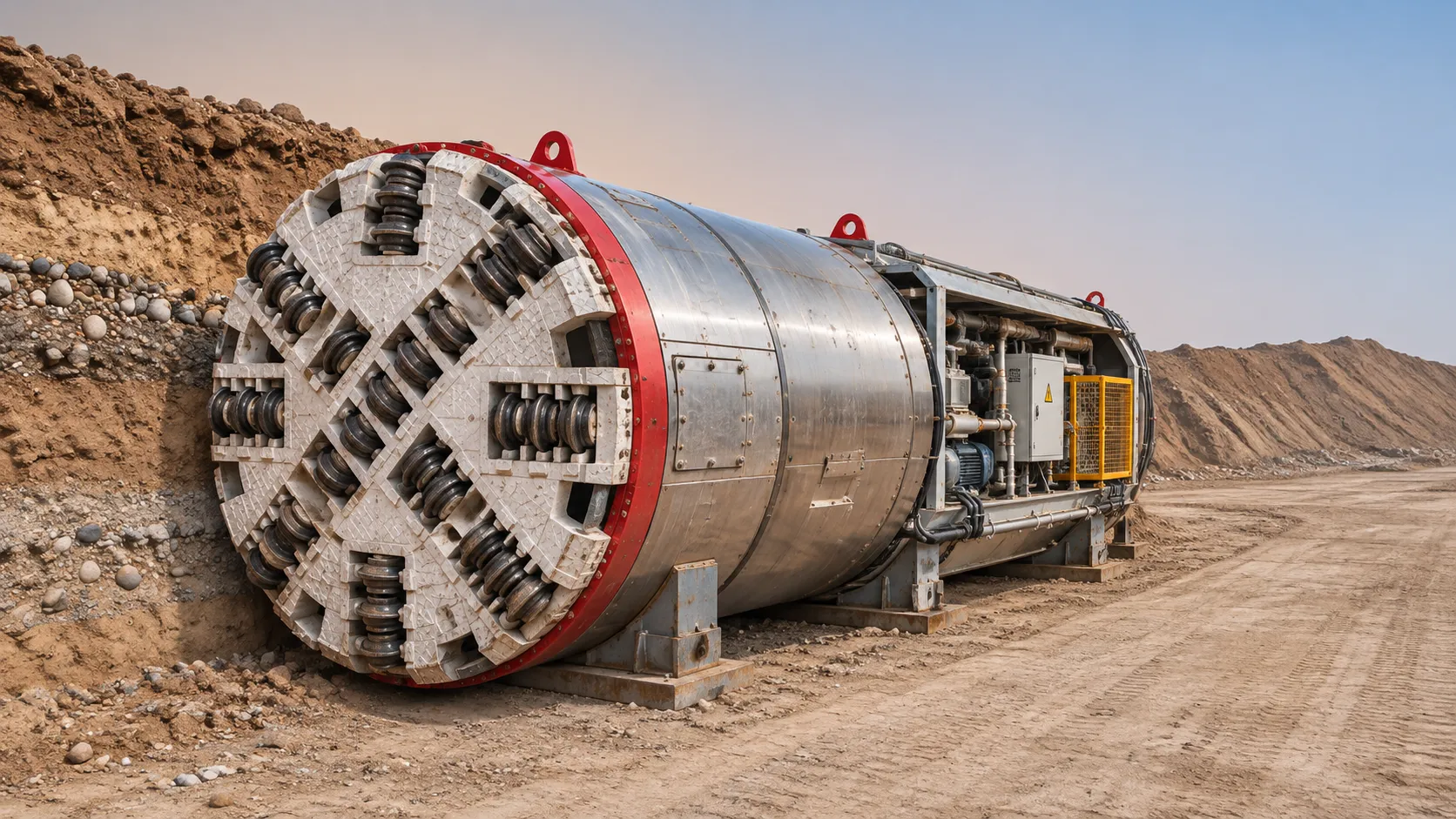
Underground Utility Construction Equipment: Choosing by Ground Conditions
Choose underground utility construction equipment with confidence. Compare trenching, HDD, microtunnelling and TBMs by ground conditions, risk and cost.

China Sets Tunnel Boring Machine Export Controls as India Pushes Local Production
China tunnel boring machine export controls could reshape procurement as India pushes local production. Explore potential supply and project impacts.
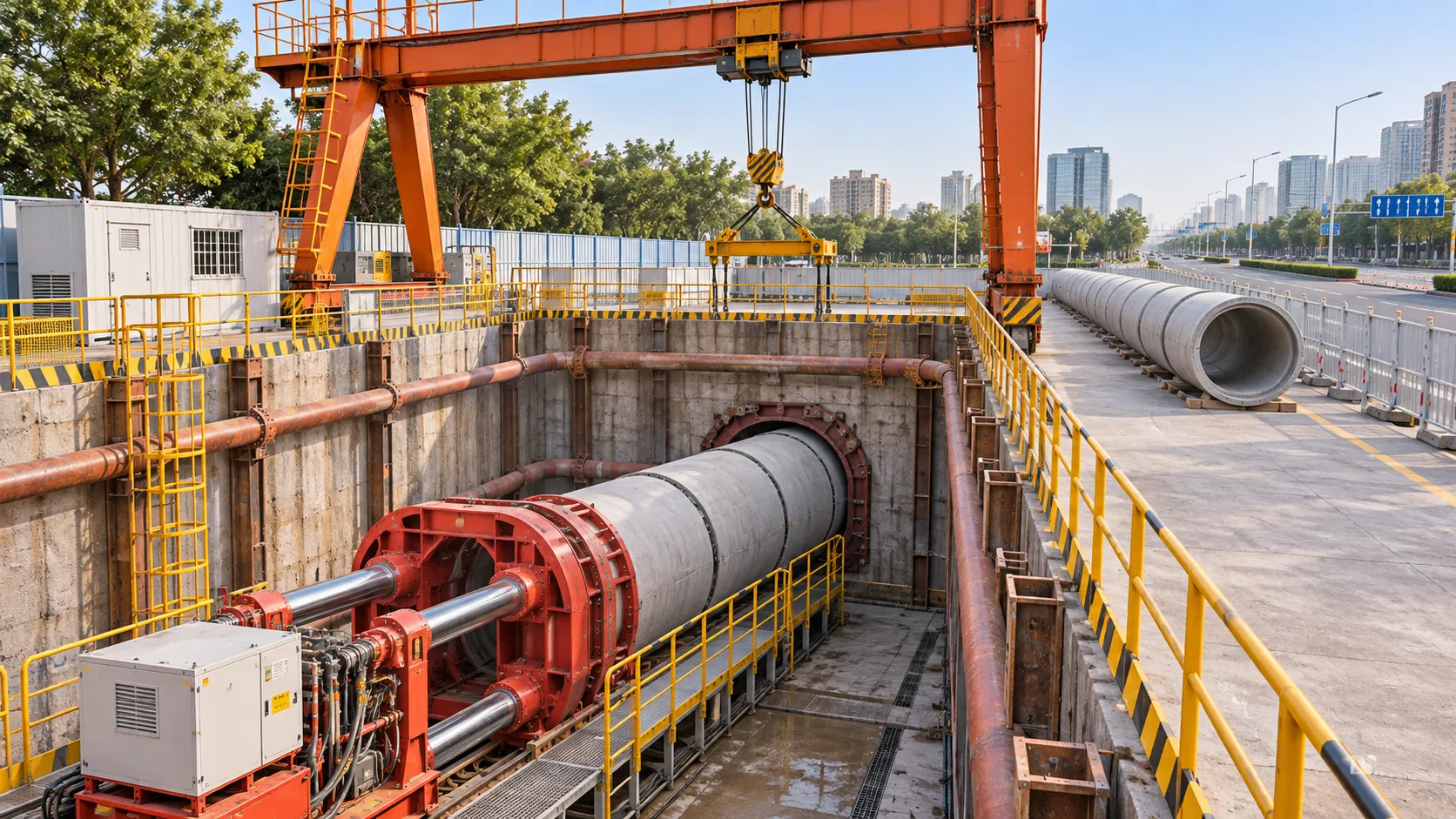
Choosing a Trenchless Pipeline Installation Contractor: Key Qualifications
Choose a trenchless pipeline installation contractor with confidence. Learn how to assess experience, equipment, safety, costs, and project risks before you hire.

China's 70% TBM Share and Export Controls Challenge India's Local Production
China's TBM export controls could challenge India's local production and infrastructure sourcing. Explore the potential risks and procurement options.
Related News
- 00
0000-00
How TBM Excavation Works in Rock and Soft Ground: A Practical Guide - 00
0000-00
Choosing a Zero-Emission Underground Equipment Supplier: What to Check - 00
0000-00
Construction Starts on Germany's Pfaffensteig Rail Tunnel, With Two TBMs Planned - 00
0000-00
How Real-Time Underground Mapping Systems Work in Tunneling - 00
0000-00
First Mechanized Tunnel Crossing Beneath the Panama Canal Completed
Weekly Insights
Stay ahead with our curated technology reports delivered every Monday.