When rock reinforcement in tunnel construction must change after blasting





Blasting does not merely remove rock; it can alter the support problem that the original round was designed to manage. A reinforcement pattern that was appropriate at the face before firing may become inadequate after the blast if the excavation exposes weaker fabric, opens joints, damages the remaining rock mass, changes groundwater inflow, or releases stress in an unexpected way.
The decision to change rock reinforcement in tunnel construction should therefore not wait for a visible fall of ground or a failed bolt. It should be made when post-blast observations show that the assumptions behind the current support class are no longer valid. The practical question is not whether the face looks rougher than expected. It is whether the changed condition affects the stability of the crown, walls, face, invert, or the next excavation cycle.
A support design is valid only while its ground assumptions remain valid
Initial support is generally based on geological investigation, probe drilling where applicable, mapped rock classes, expected discontinuity patterns, groundwater conditions, excavation span, blast method, and the sequence of advance. These inputs establish a working support regime: bolt length and spacing, shotcrete thickness, mesh or fibre reinforcement, lattice girders or ribs, face support, spiling, drainage, and the timing of closure.
That regime is not a permanent instruction detached from field conditions. Drill-and-blast tunnels are governed by the observational relationship between predicted ground and exposed ground. Each blast reveals a new section of rock mass, while the blast itself may create a damaged perimeter zone beyond the intended excavation line. The project must distinguish between a local excavation-quality issue and a condition that changes the load path or deformation behaviour of the surrounding rock.
A small area of isolated overbreak in competent, blocky rock may call for scaling and local filling. Repeated overbreak around the crown, combined with newly opened joints and loose wedges, points to a different issue: the rock mass may no longer be capable of forming the stable arch assumed in the original support arrangement. In that situation, simply replacing lost shotcrete volume does not restore the original design basis.
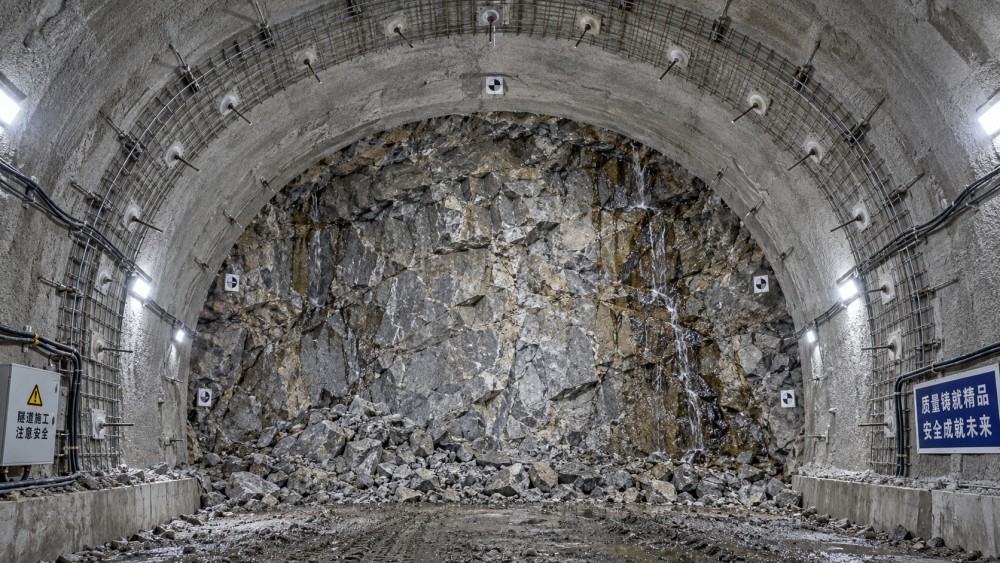
Post-blast signs that require an immediate reassessment
Not every deviation requires redesign, but several observations should trigger a formal review before normal advance continues. The most important are changes that are persistent, spatially connected, or accompanied by displacement, water, or difficulty in installing support.
Overbreak that changes the excavation geometry
Overbreak matters because it increases unsupported span, removes confinement at the perimeter, and can leave an irregular profile that is difficult to support effectively with a nominal shotcrete thickness. It is especially significant at the crown and upper haunches, where gravity-driven blocks and loosening zones can develop.
The relevant measure is not only the total excavated volume. The team needs to know where the overbreak occurred, whether it follows a structural plane, whether it repeats from round to round, and whether it was caused by blast energy, poor contour-hole performance, weak rock, or a combination of these. A local blast-control correction may be sufficient if the surrounding rock remains intact. If the blast has exposed a sheared, weathered, or intensely jointed band, reinforcement needs may change independently of the blast adjustment.
Newly exposed discontinuities and unstable block geometry
Rock can appear sound in a face mapping record while still being vulnerable to wedge failure after excavation. The key issue is the orientation, persistence, spacing, aperture, infilling, and water condition of joints, bedding, foliation, faults, and shear surfaces. A set of planes that daylight into the opening can create detachable blocks at the crown or sidewall even where intact rock strength is high.
A change is warranted when the exposed structures create a failure geometry that the existing bolt pattern cannot reliably stitch across. This may mean longer anchors to reach competent rock behind the potential failure surface, reduced bolt spacing, altered bolt orientation, systematic mesh, or earlier shotcrete application. The appropriate response depends on the block geometry; adding more bolts on the same grid without addressing bolt embedment length or direction can leave the actual release plane unrestrained.
Fracturing beyond the expected blast-damaged zone
Blast-induced damage is expected to some degree, particularly in hard brittle rock. The concern begins when radial cracking, slabbing, loosened rock, or loss of ringing sound extends farther into the perimeter than anticipated, or when drilling for bolts encounters unusually broken ground. Such observations may indicate excessive perimeter charge, adverse geological fabric, stress-related damage, or an interaction between these factors.
The response should separate excavation control from reinforcement control. Reducing charge concentration, improving decoupling, refining contour drilling, or changing delay sequencing may limit further damage. Yet the already excavated round still needs support suited to its present condition. If a loosened annulus has developed, the project may need immediate sealing shotcrete, mesh, closer bolt spacing, or a temporary support element before the next blast.
Unexpected convergence, cracking, or load development
Deformation is often the clearest evidence that the rock-support system is behaving differently from the design expectation. Warning signs include accelerating convergence, crown settlement, closure at the haunches, cracking or debonding of fresh shotcrete, distortion of ribs, bolt plate movement, or repeated loss of tension in installed elements.
Magnitude alone is not enough. A measured movement may be acceptable if it stabilizes within the project’s defined observational criteria. More concerning is the rate and trend: movement that continues after support installation, resumes after the next adjacent blast, or accelerates as the face advances indicates that the support may not be mobilizing quickly enough or that the excavation sequence is exposing more ground than the system can carry.
In squeezing or stress-sensitive ground, a rigid increase in support is not automatically the correct answer. The design may need a system that accommodates controlled deformation while preserving confinement and avoiding sudden support failure. The required change must be based on the ground behaviour model, not on a generic preference for heavier steel.
Water changes that degrade rock mass behaviour
A new seepage path after blasting can transform a stable-looking rock mass into a support-critical condition. Water may reduce the shear resistance of infilled joints, soften weak seams, wash fines from fractures, increase pressure behind shotcrete, or make bolt installation unreliable. Water inflow can also signal a faulted zone or a permeable fracture network extending beyond the face.
Where water affects stability, drainage and reinforcement must be designed together. Sealing the surface with shotcrete without drainage can trap pressure behind the lining. Conversely, drainage alone does not secure blocks that have already been released along lubricated discontinuities. The review should establish the source, pressure condition, likely persistence, and interaction with the planned final waterproofing and lining system.
When a local correction becomes a support-class change
One of the most costly errors in tunnel execution is treating a repeated geological signal as a sequence of isolated incidents. Local scaling, a few supplementary bolts, and extra shotcrete may be justified for a short anomaly. They become inadequate when the condition persists across multiple rounds, widens laterally, appears in probe holes, or produces a consistent deformation response.
A support-class change is generally justified when one or more of the following conditions is established:
- The exposed rock quality, structure, or groundwater condition falls outside the assumptions used for the current support design.
- The geometry of potential wedges or loosened zones exceeds the anchorage reach or coverage of the installed system.
- Monitoring shows that displacement rate, support distress, or convergence trend is beyond the project’s predefined action criteria.
- The blast has created a damaged perimeter that cannot be safely managed by routine scaling and surface treatment.
- The next excavation round would enlarge an already unstable zone before the current support has achieved sufficient capacity.
This distinction matters commercially as well as technically. A documented support-class change establishes why added bolts, shotcrete, steel sets, forepoling, face measures, or reduced advance lengths are necessary. Without a clear record linking the changed ground condition to the modified support requirement, teams may later argue over whether extra support resulted from foreseeable conditions, blast execution, or an unrecognized geological variation.
Make the decision from a disciplined post-blast evidence set
Decisions made underground are time-sensitive, but they should not rely on a single visual impression. A practical assessment combines observations from the face, excavation profile, support installation, monitoring, and available forward investigation. The objective is to establish a defensible picture quickly enough to protect the crew and avoid advancing into a worsening condition.
Face mapping should be completed before fresh shotcrete obscures the evidence, while still allowing scaling and crew protection to take priority. The record should identify not only a rock-quality category but also structural orientation, fault or seam contacts, water, blast damage, block sizes, overbreak location, and any difference between the planned and actual support installation. Photographic records, profile scans, convergence readings, and drill logs make later interpretation more reliable.
The engineering review should then answer a limited set of operational questions: Is the installed support sufficient for the exposed condition? Can the next round proceed at the planned length? Does support need to be installed closer to the face? Must the excavation sequence change to control deformation or prevent loosening? Is the condition local, or does it require forward probing and a revised support regime for an upcoming zone?
Support changes must match the failure mechanism
“Increase reinforcement” is not a complete engineering instruction. Different mechanisms require different interventions, and poorly matched support can consume time without controlling the relevant risk.
For structurally controlled block failure, fully grouted rock bolts, cable bolts, mesh, straps, and shotcrete work by tying blocks into a stable rock mass and retaining smaller fragments. Their layout must intersect the discontinuities that define the potential wedge. In highly fractured ground, shotcrete provides surface confinement, but it may need mesh, fibres, or lattice elements where the rock cannot bridge between bolts.
For weak, faulted, or ravelling ground, the critical issue may be preventing loss of material ahead of and around the face. Shorter blast rounds, immediate shotcrete, face bolting, spiles, forepoling, pipe umbrella systems, or staged excavation may be more important than simply increasing the capacity of support installed behind the face. The decision hinges on whether instability is occurring in the exposed perimeter, ahead of the face, or both.
For stress-driven slabbing or squeezing, the system must be assessed as an interaction between rock deformation and support response. Earlier ring closure, invert closure, yielding elements, modified support timing, reduced round length, and changes to excavation shape can be more effective than isolated reinforcement additions. A stiff system placed too late may crack after significant convergence has already occurred; a flexible system without adequate confinement may permit damaging closure.
For water-bearing fractured zones, anchorage reliability becomes a central concern. Drilling, hole cleaning, grout selection, installation timing, and quality verification all influence whether nominal bolt capacity is actually available. Support drawings alone cannot resolve installation problems created by unstable, wet holes.
Do not confuse blast optimization with ground-support redesign
Blast quality and reinforcement are connected, but they are not interchangeable controls. Poor contour blasting can produce overbreak, cracked perimeter rock, and excessive scaling requirements. Improving the drill pattern, charge distribution, decoupling, stemming, and timing can reduce future damage. It cannot guarantee that a structurally adverse or weak geological zone will become self-supporting.
Equally, heavier reinforcement should not become a substitute for correcting a blast pattern that repeatedly damages otherwise competent rock. This approach increases material use, slows the cycle, and may conceal the source of avoidable instability. The post-blast review should therefore assign findings to three categories: geology-driven, blast-driven, and interaction-driven. Many difficult sections fall into the third category, where adverse fabric makes the perimeter especially sensitive to energy concentration and contour drilling accuracy.
Control the schedule by defining hold points before conditions deteriorate
Schedule pressure often encourages teams to treat support revision as a delay. In reality, the greater delay is created when advance continues through a changing ground zone without sufficient confirmation, resulting in extended scaling, rework, fall-of-ground exposure, damaged support, or a forced stoppage later.
Useful hold points are not arbitrary pauses. They are decision gates linked to observable conditions: completion of scaling and face mapping; confirmation of required primary support; review of convergence trends before another adjacent blast; probe-drilling results before entering an inferred fault or water-bearing zone; and verification that the support ring has achieved the required continuity before excavation undermines it.
These gates work only if authority is clear. The shift team needs defined criteria for stopping work and installing contingency support. The geological and engineering functions need a fast route for classifying the condition. The project record needs to capture the basis for releasing the next round. A support response that arrives after the face has advanced beyond the unstable section is rarely an efficient response.
The essential management test
Rock reinforcement must change after blasting when the exposed ground, measured behaviour, or excavation damage shows that the current support arrangement no longer controls the credible failure mechanism at the required stage of advance. The decision should be based on mapped evidence, profile condition, water observations, support performance, and deformation trends—not on visual alarm alone and not on the assumption that the next blast will restore normal conditions.
The most resilient tunnel operations treat every blast as both an excavation event and a verification point for the ground model. That discipline keeps reinforcement aligned with the rock actually surrounding the opening, preserves the integrity of the support cycle, and prevents a manageable deviation from becoming a major stability and programme problem.
Related News
Tunnel Boring Machine Costs: Budgeting for Purchase, Operation, and Project Risk
Tunnel Boring Machines cost more than purchase price. Learn how to budget lifecycle costs, downtime, logistics, wear, and project risk for smarter TBM decisions.
Open-Pit Haulage Cost Analysis: How Mine Managers Can Cut Cost per Tonne
Open pit haulage cost analysis: discover practical ways to reduce cost per tonne through payload control, cycle-time optimization, road performance, and smarter fleet decisions.
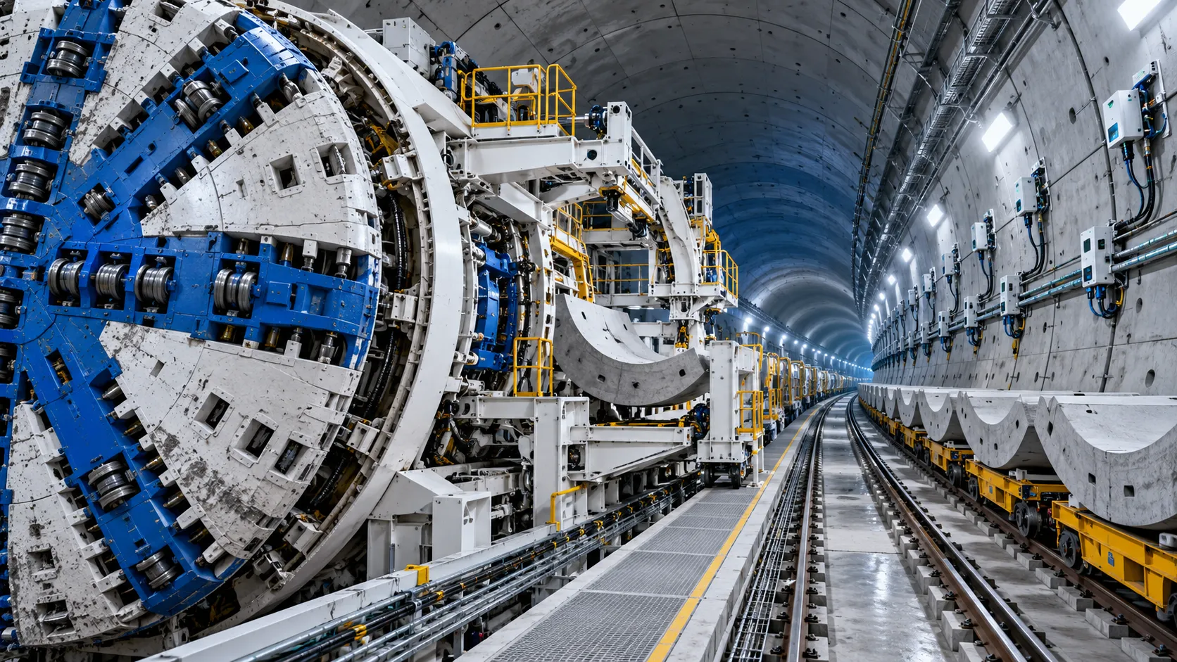
Tunnel Construction Innovations That Reduce Risk and Schedule Delays on Urban Projects
Tunnel construction innovation for urban projects: discover smarter TBMs, real-time monitoring, trenchless methods, and automation that reduce risk and protect schedules.
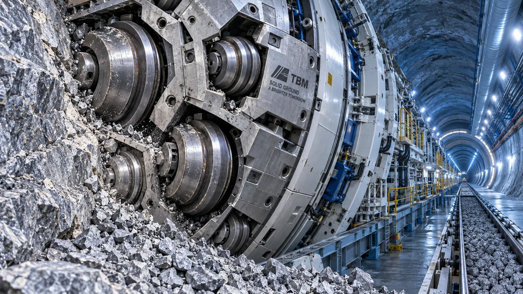
TBM Disc Cutter Design: Key Geometry and Load Factors for Hard Rock Tunnelling
TBM disc cutter design explained: explore geometry, spacing, load distribution and maintenance factors for reliable, efficient hard-rock tunnelling performance.
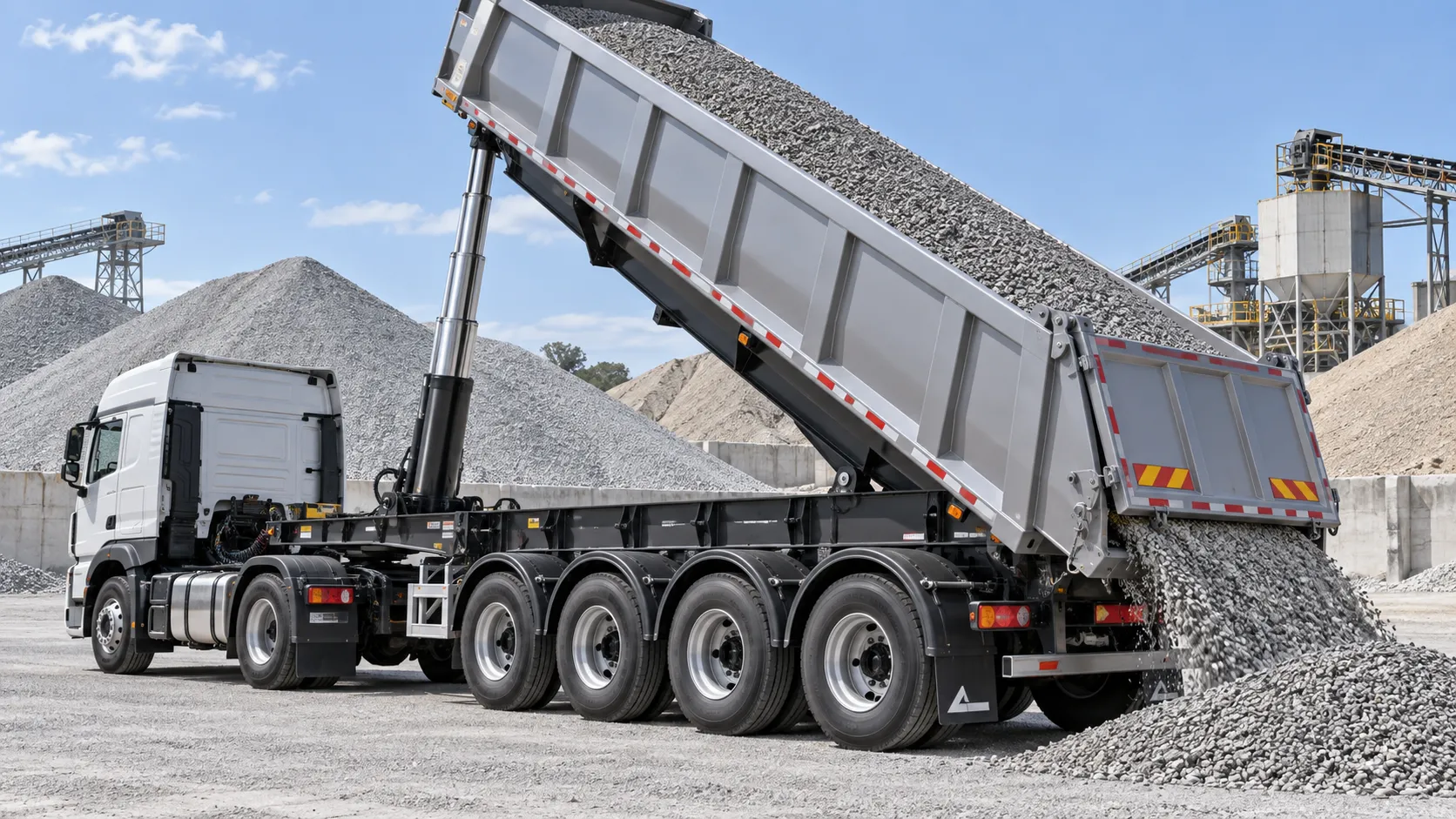
Hydraulic Tipping Stability Risks in Multi-Axle Dump Special Trailers
Dump special trailers: discover key hydraulic tipping stability risks, multi-axle load dynamics, and practical safety controls for safer, smarter bulk hauling.
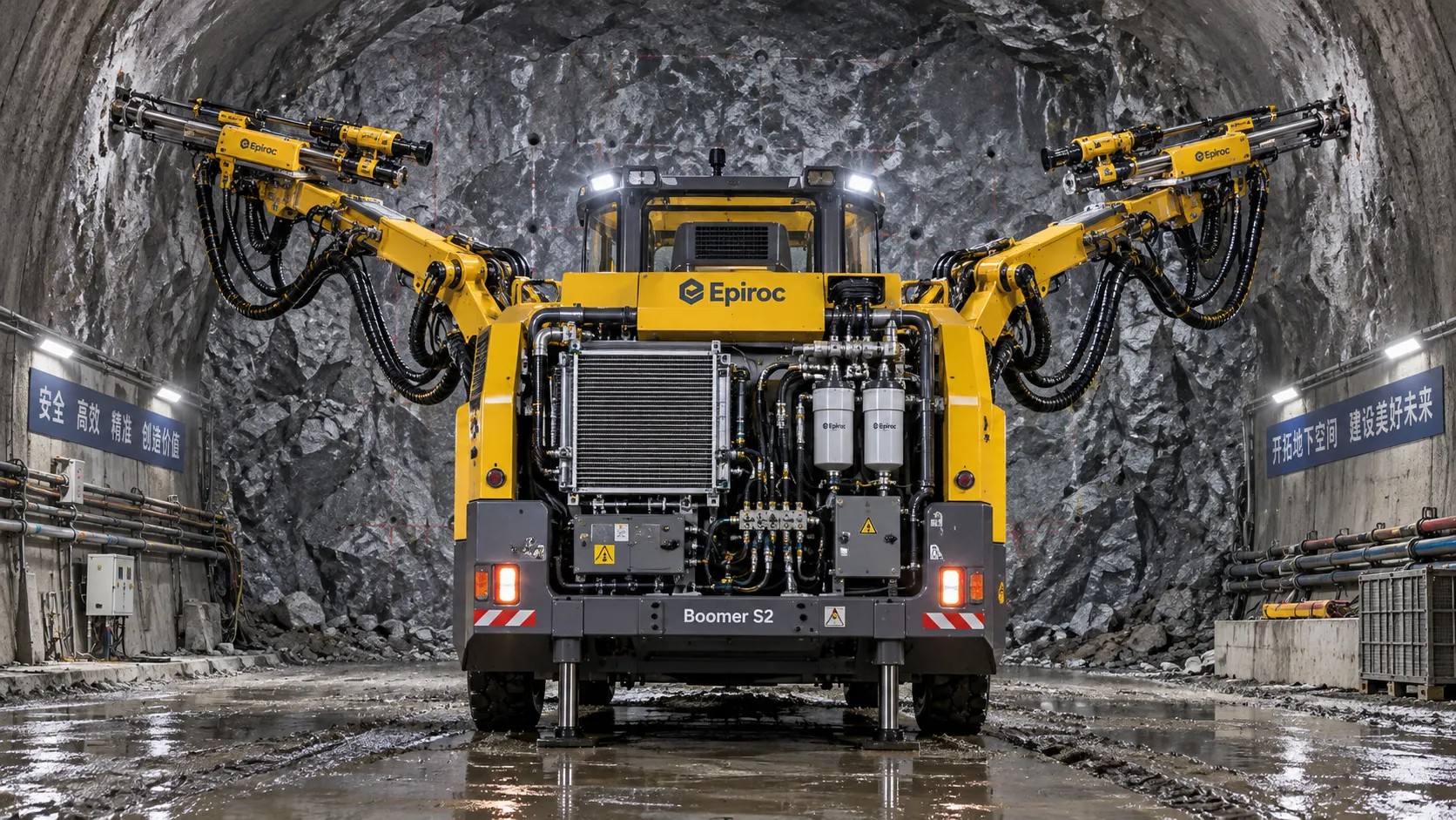
How tunnel hydraulic systems influence drill jumbo uptime underground
Tunnel hydraulic systems directly influence drill jumbo uptime. Explore how stable pressure, clean oil, cooling, and maintainable design reduce underground downtime.
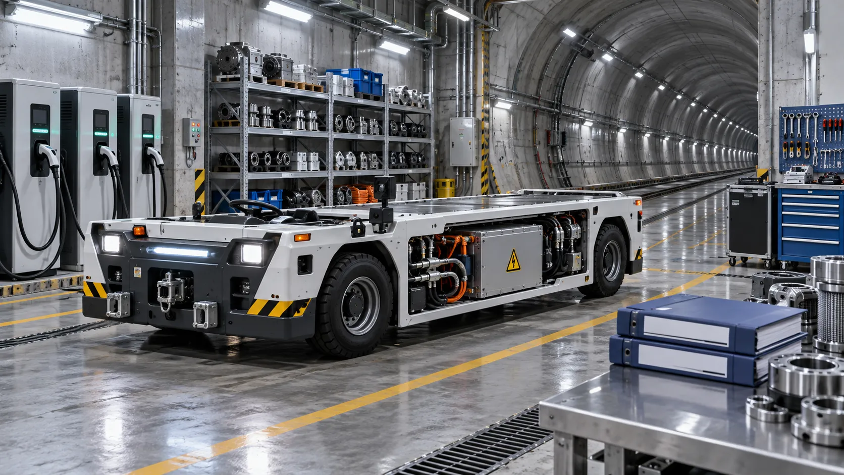
What to verify before appointing a tunneling vehicles manufacturer
Choosing a tunneling vehicles manufacturer? Verify application fit, reliability, compliance, parts support, training, and channel terms before appointing a partner.
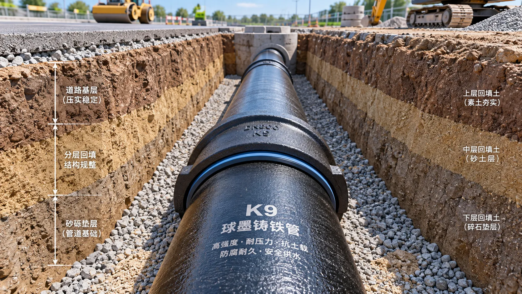
Selecting K9 Ductile Iron Pipe for Buried Water Pipeline Conditions
K9 ductile iron pipe selection for buried water pipelines: compare pressure duty, joints, soil loads, corrosion protection, and installation controls for reliable long-term performance.
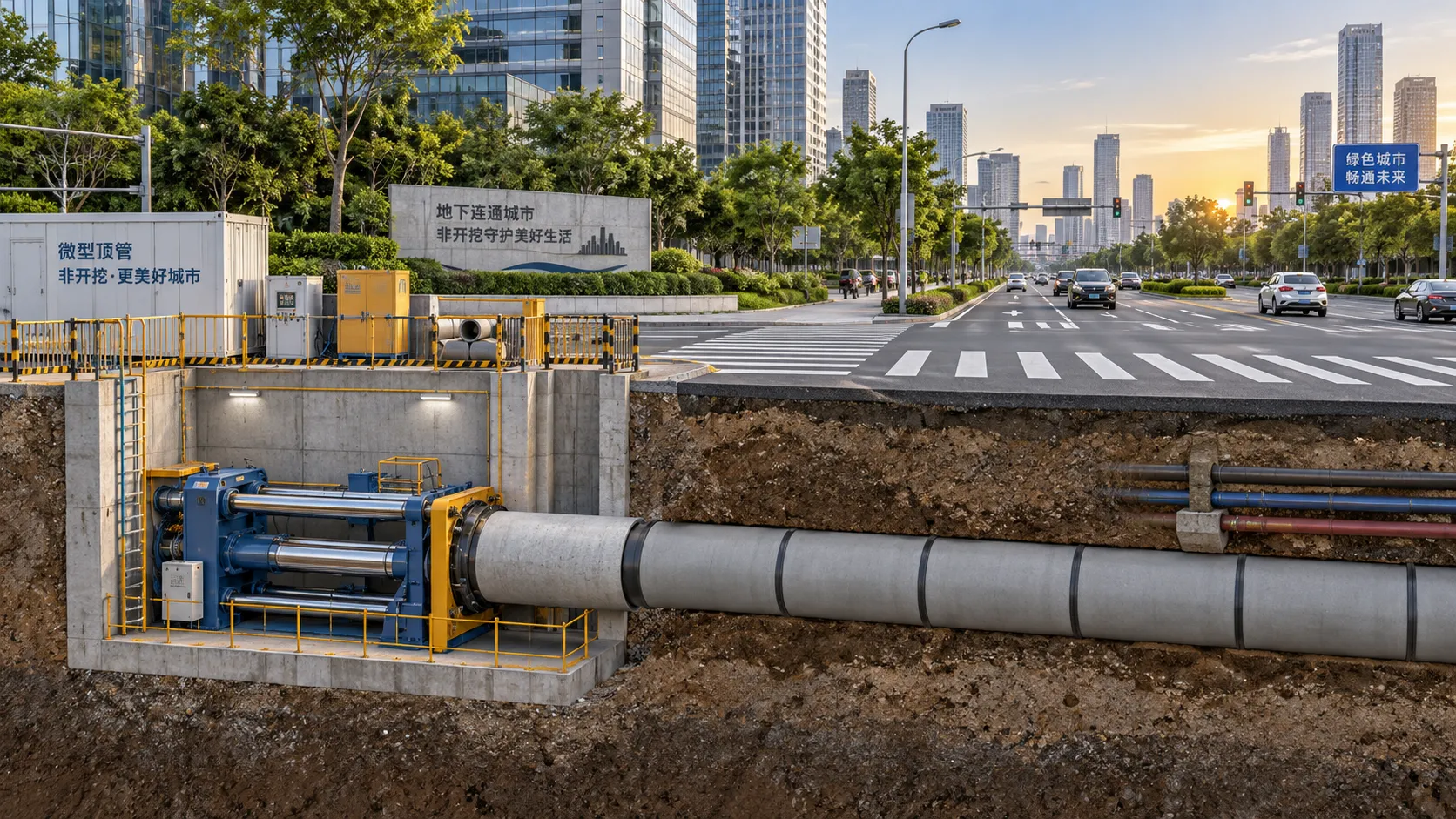
Where Trenchless Technology Delivers the Best Value in Urban Utility Projects
Trenchless Technology applications deliver high value in urban utility projects by reducing disruption, protecting critical crossings, and improving project outcomes.
Related News
- 00
0000-00
Tunnel Boring Machine Costs: Budgeting for Purchase, Operation, and Project Risk - 00
0000-00
Open-Pit Haulage Cost Analysis: How Mine Managers Can Cut Cost per Tonne - 00
0000-00
Tunnel Construction Innovations That Reduce Risk and Schedule Delays on Urban Projects - 00
0000-00
TBM Disc Cutter Design: Key Geometry and Load Factors for Hard Rock Tunnelling - 00
0000-00
Hydraulic Tipping Stability Risks in Multi-Axle Dump Special Trailers
Weekly Insights
Stay ahead with our curated technology reports delivered every Monday.