
How tunnel hydraulic systems influence drill jumbo uptime underground





Drill jumbo uptime underground is often discussed as a maintenance issue, but the hydraulic system is usually where availability is won or lost. A jumbo can have sound booms, modern controls, and capable rock drills, yet still miss drilling cycles when hydraulic pressure fluctuates, oil overheats, contamination damages precision components, or a small hose failure becomes difficult to repair at the face.
Tunnel hydraulic systems do more than transmit power. They determine whether the rock drill receives stable impact energy, whether feed and boom motions remain controllable, and whether the machine can complete a shift without an interruption that disrupts the entire drill-and-blast sequence. The practical question is not simply whether a hydraulic circuit has sufficient rated pressure. It is whether it can preserve the required pressure, flow, temperature, and cleanliness under the actual underground duty cycle.
Uptime depends on hydraulic stability, not peak output alone
A drill jumbo performs several hydraulic jobs at once: high-frequency percussion, drill rotation, feed motion, boom positioning, stabilizer movement, and sometimes bolting or service functions. These functions may share pumps, reservoirs, cooling capacity, filters, valve blocks, and return lines. When the system is designed or maintained around nominal operating conditions only, problems tend to appear during combined loading: drilling hard rock while one or more booms are positioned, operating in high ambient temperature, or working through long shifts with limited cooling time.
Stable pressure is especially important at the rock drill. Pressure loss, slow pressure recovery, or excessive ripple can reduce impact consistency. The visible result may be slower penetration, irregular drilling behavior, reduced hole quality, or operators compensating through changes in drilling parameters. That compensation can hide a hydraulic fault for a while, but it often transfers stress to drill consumables, seals, pumps, or the rock drill itself.
Pressure stability must also be considered together with flow. Pressure provides force; flow determines actuator speed and supports the energy demand of the drilling circuit. A pump that reaches pressure but cannot sustain adequate flow under load may allow the jumbo to start a cycle normally and then lose drilling efficiency as oil warms or multiple functions operate. In uptime terms, this produces a more subtle loss than a total breakdown: the machine remains available on paper while advance per shift declines.
Why underground conditions accelerate hydraulic failures
Hydraulic equipment in a tunnel operates in conditions that are unfavorable to fluid power systems. Rock dust, water spray, poor access, vibration, variable ambient temperature, and repeated high-load drilling all increase the chance that a manageable defect becomes unplanned downtime. Surface maintenance assumptions rarely transfer directly underground.
Contamination is one of the most damaging issues because it affects parts that depend on narrow internal clearances. Fine particles can score pump components, erode valve edges, impair proportional control, and cause spools to stick or respond inconsistently. Water can reduce lubricity, promote corrosion, and alter the behavior of additives in the oil. Neither problem needs to cause an immediate failure to be costly. Wear can gradually increase internal leakage, forcing the system to generate more heat while delivering less usable hydraulic energy.
Heat is often the next link in the failure chain. Hydraulic oil temperature rises when energy is lost through throttling, leakage, inadequate cooler performance, blocked airflow, or a pump working inefficiently. Hot oil loses viscosity, which can reduce the lubricating film in pumps and motors and increase leakage across worn clearances. Seal life may also shorten. A temporary overheating alarm should therefore not be treated only as a cooling issue; it may indicate an underlying efficiency or control problem elsewhere in the circuit.
Access changes the repair consequence. A hose seepage or contaminated filter may be relatively easy to correct in a workshop. At an active heading, the same issue can require travel, isolation, cleanup, parts retrieval, and re-commissioning under constrained conditions. The downtime impact is shaped by maintainability as much as by component reliability.
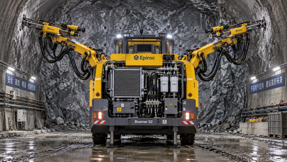
The hydraulic features that most affect drill jumbo availability
When comparing tunnel hydraulic systems, it is useful to assess the circuit as a working system rather than as a list of branded components. Several design choices have a direct effect on uptime.
Load management and function separation
Hydraulic circuits must allocate available flow and pressure without allowing one operation to destabilize another. A system that gives drilling functions clear priority can maintain more predictable drill performance when booms, feeds, or auxiliary functions are active. The correct approach depends on the jumbo configuration and expected operating pattern. A multi-boom machine working several faces has different simultaneous-demand behavior from a compact single-boom unit.
Function separation can improve fault isolation as well. If a fault in an auxiliary circuit forces the entire drilling package out of service, a minor defect becomes a production stoppage. Isolation valves, logical circuit grouping, accessible test points, and controls that identify the affected function help maintenance teams narrow the fault before replacing components unnecessarily.
Filtration that reflects the contamination path
Adding a filter is not the same as controlling contamination. The evaluator should examine where oil enters the system, where it returns, and what happens during servicing. Return-line filtration is useful, but it cannot fully protect a pump from contamination introduced through damaged cylinder seals, breather failures, incorrect top-up practices, or unclean service tools.
A well-considered arrangement commonly includes protected fluid filling, reservoir breathers suited to the environment, filtration at appropriate locations, and a practical way to inspect filter condition. The critical point is serviceability. A filter element that is difficult to reach or change underground may remain in use beyond its effective interval, creating pressure drop and bypass risk precisely when the system is under greatest stress.
Cleanliness targets should be defined for the machine and its components, not borrowed from an unrelated hydraulic application. High-response valves and modern drilling controls may require more disciplined fluid cleanliness than simple low-speed actuators. The supplier’s component requirements, fluid specification, sampling method, and corrective actions should be part of the acceptance and maintenance documentation.
Cooling capacity in the actual tunnel environment
Cooling systems are frequently assessed under ideal airflow and clean radiator conditions. Underground use is different. Dust accumulation, restricted air movement, recirculating heat, and high machine utilization can reduce cooling margin. The question is not whether the cooler is installed; it is whether the hydraulic oil stays within its intended operating range while the jumbo performs sustained drilling in the expected site conditions.
Cooler placement and access matter. Heat exchangers exposed to dust or mud need an inspection and cleaning routine that can be performed without major disassembly. Temperature monitoring should distinguish normal warm-up from persistent thermal loading. A sensor that only triggers a shutdown alarm provides less operational value than trend data that shows temperatures rising progressively over comparable drilling cycles.
Hoses, fittings, and routing at the boom
Hose failures are among the most disruptive field events because they can cause oil loss, cleanup work, safety exposure, and immediate loss of machine function. On a drill jumbo, hoses near articulated booms and feeds are repeatedly flexed, exposed to abrasion, and subject to vibration. Routing must account for the full motion envelope, not merely the parked position.
Protective sleeves and guards help only when they do not trap moisture, conceal leaks, or create abrasive contact points of their own. The better assessment is a physical inspection of bend radius, clamp placement, rubbing points, access for inspection, and protection around predictable impact zones. Standardizing hose sizes and fittings can also reduce downtime where onsite spare holdings are limited, provided the standardization does not compromise the duty rating or routing requirements.
Hydraulic symptoms should be interpreted as system signals
Maintenance teams lose time when each symptom is treated as an isolated component failure. A slow feed, hot oil, noisy pump, drifting boom, and inconsistent percussion can be related. Replacing the visibly affected part without checking the wider hydraulic condition may restore operation briefly while the root cause remains active.
This system view is also useful when reviewing machine telemetry. Pressure, temperature, filter condition, pump control signals, and fault history become more valuable when they are read against drilling hours, rock conditions, use of multiple booms, and maintenance events. A single temperature value is less informative than a recurring rise under the same duty pattern. Likewise, a pressure fault code has limited value until it is linked to the function being commanded and the load at that moment.
Specify maintainability alongside performance
A common procurement error is to focus on drilling power, boom coverage, and automation features while treating hydraulic maintenance as a service detail. Underground uptime depends heavily on how quickly common work can be completed. The evaluation should include access to filters, sampling points, drain connections, coolers, valve blocks, pumps, and hose assemblies. It should also cover the practical isolation of circuits and the risk of contaminating the system during ordinary servicing.
Service documentation should make the hydraulic architecture understandable at the level required for fault diagnosis. This includes circuit diagrams, component identification, test locations, fluid requirements, alarm logic, and procedures for restoring the machine after a component replacement. A machine that requires proprietary intervention for every pressure or sensor-related issue may be suitable in a well-supported fleet, but it creates a different availability risk at remote or fast-moving tunnel projects.
Spare-parts strategy should follow failure consequence, not just purchase cost. Some parts are inexpensive but have little operational effect if unavailable. Others, such as a critical hose assembly, filter element, sensor, seal kit, valve coil, or pump-control component, can stop drilling even though their individual value is modest compared with the machine. The useful question is: which hydraulic items can prevent a shift from being completed, and can they be safely installed with the resources available underground?
A practical acceptance approach for tunnel hydraulic systems
Before selecting a drill jumbo or approving a hydraulic upgrade, assess the system under the expected duty cycle rather than only during a short unloaded demonstration. The review should establish how the machine behaves when drilling demand is sustained and other functions are used as they would be at the face.
- Map the operating sequence: drilling, repositioning, collaring, feed movement, boom adjustment, flushing, and any bolting functions.
- Identify concurrent hydraulic demands and confirm which functions receive priority when demand exceeds normal flow capacity.
- Review fluid cleanliness control from oil delivery through filling, breathing, filtration, sampling, and component replacement.
- Check temperature behavior during representative work, including cooler access and the response to rising oil temperature.
- Inspect hose routing through full boom movement and confirm that recurring wear locations can be accessed and repaired.
- Confirm that pressure, temperature, and filter-condition data can support diagnosis rather than merely report a shutdown.
- Evaluate the availability of critical service parts and the time needed to isolate, repair, test, and return the machine to drilling.
This approach prevents an important misunderstanding: reliability does not come from oversizing every hydraulic component. Excess capacity can be useful where peak demand genuinely requires it, but poor contamination control, weak cooling, inaccessible service points, or uncontrolled pressure transients can still reduce uptime. A balanced design, matched to the jumbo’s drilling duty and tunnel conditions, is more valuable than impressive standalone specifications.
Automation changes the evidence available, not the underlying hydraulic requirements
Modern drilling jumbos increasingly combine electro-hydraulic controls, automated drilling plans, positioning assistance, and machine data collection. These functions can improve repeatability and make hydraulic degradation easier to detect early, but they also increase the importance of signal quality and control stability. A sensor fault, degraded pilot circuit, or sticking proportional valve can appear as a software or positioning issue even when the origin is hydraulic.
For this reason, condition monitoring should connect control data with fluid-power behavior. Trending oil temperature, pressure response, filter condition, pump command behavior, and repeated fault patterns can support planned intervention before drilling is interrupted. It should not become a substitute for oil analysis, hose inspection, cooler cleaning, and hands-on checks of leakage and abnormal noise.
UTMD’s coverage of drilling jumbos, tunnel machinery, and smart underground equipment reflects a broader operational reality: digital capability only improves asset utilization when the physical systems beneath it remain dependable. For drill jumbos, hydraulic integrity is one of those foundations.
The strongest decision criterion is therefore straightforward. Choose and maintain a hydraulic system that can deliver controlled drilling energy through sustained underground duty, keep its oil clean and cool, expose failures early, and allow routine repairs to be completed without turning a minor defect into a lost production shift. That is how hydraulic design moves from being a specification-sheet item to a measurable contributor to drill jumbo uptime.
Related News
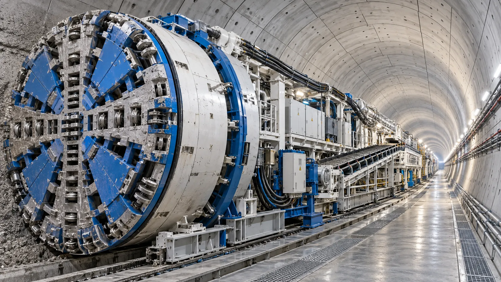
Tunnel Boring Machine Costs: Budgeting for Purchase, Operation, and Project Risk
Tunnel Boring Machines cost more than purchase price. Learn how to budget lifecycle costs, downtime, logistics, wear, and project risk for smarter TBM decisions.

Open-Pit Haulage Cost Analysis: How Mine Managers Can Cut Cost per Tonne
Open pit haulage cost analysis: discover practical ways to reduce cost per tonne through payload control, cycle-time optimization, road performance, and smarter fleet decisions.
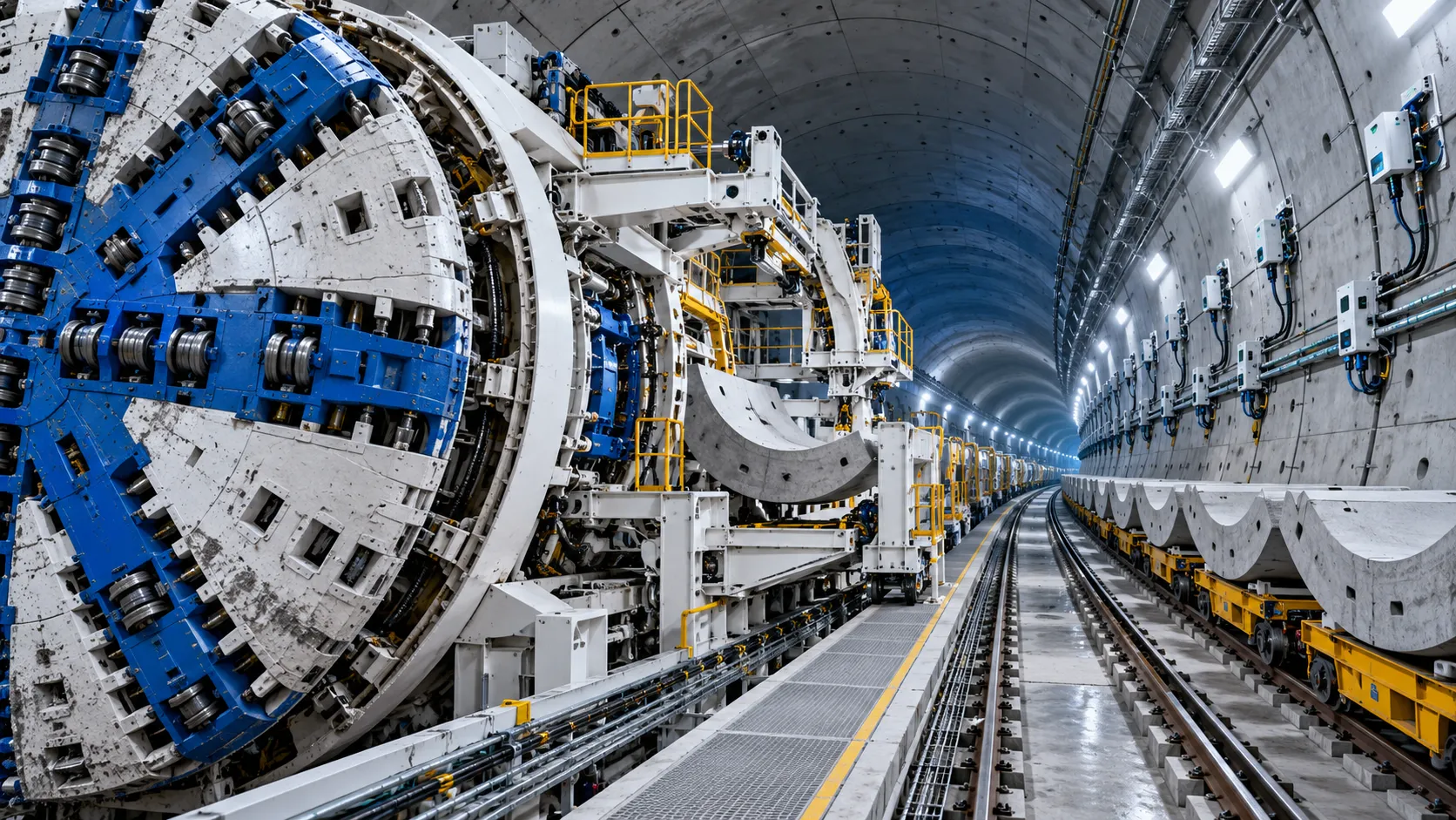
Tunnel Construction Innovations That Reduce Risk and Schedule Delays on Urban Projects
Tunnel construction innovation for urban projects: discover smarter TBMs, real-time monitoring, trenchless methods, and automation that reduce risk and protect schedules.
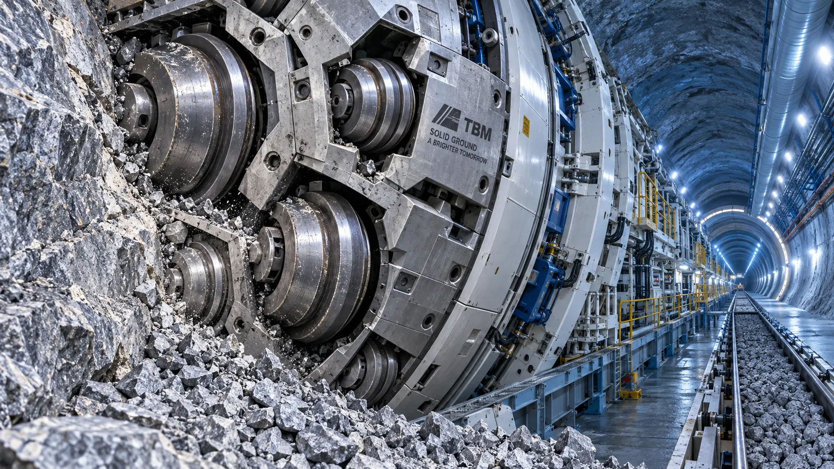
TBM Disc Cutter Design: Key Geometry and Load Factors for Hard Rock Tunnelling
TBM disc cutter design explained: explore geometry, spacing, load distribution and maintenance factors for reliable, efficient hard-rock tunnelling performance.
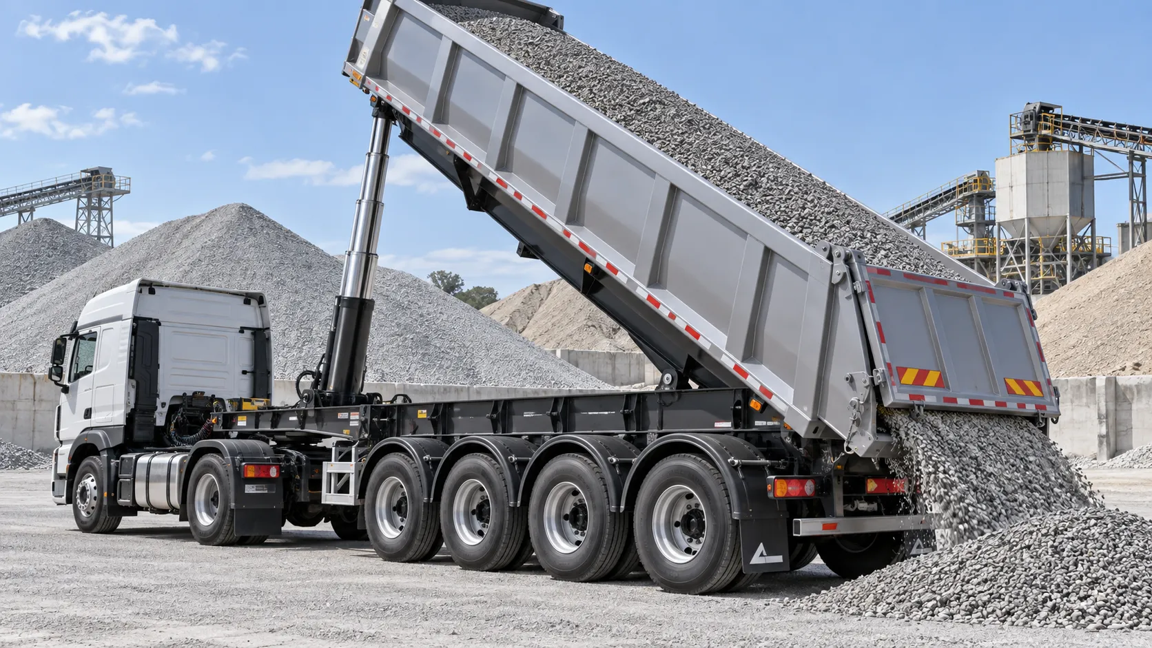
Hydraulic Tipping Stability Risks in Multi-Axle Dump Special Trailers
Dump special trailers: discover key hydraulic tipping stability risks, multi-axle load dynamics, and practical safety controls for safer, smarter bulk hauling.
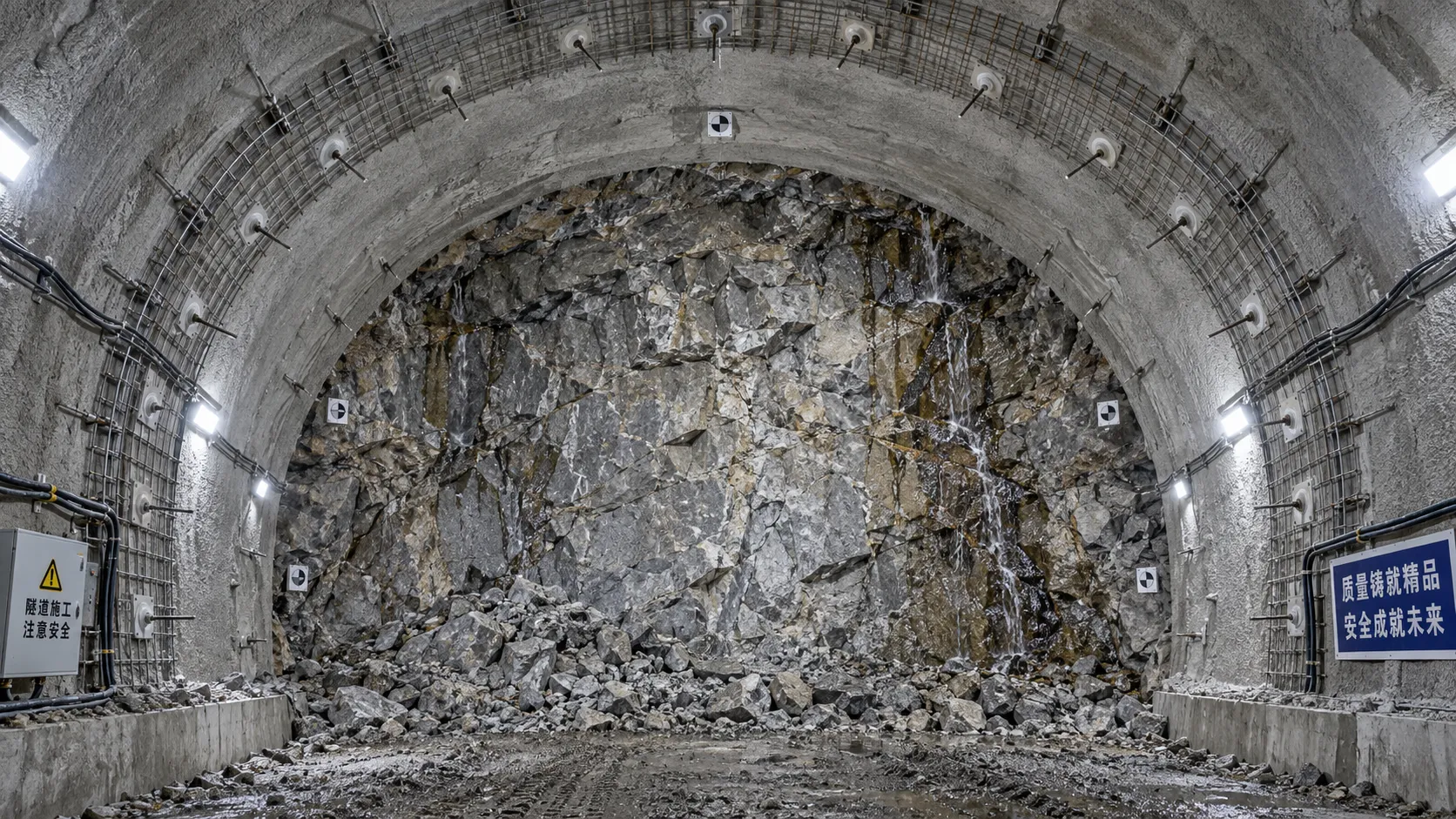
When rock reinforcement in tunnel construction must change after blasting
Rock reinforcement in tunnel construction must change when blasting reveals overbreak, weak joints, water inflow, or deformation. Discover key post-blast support decisions.
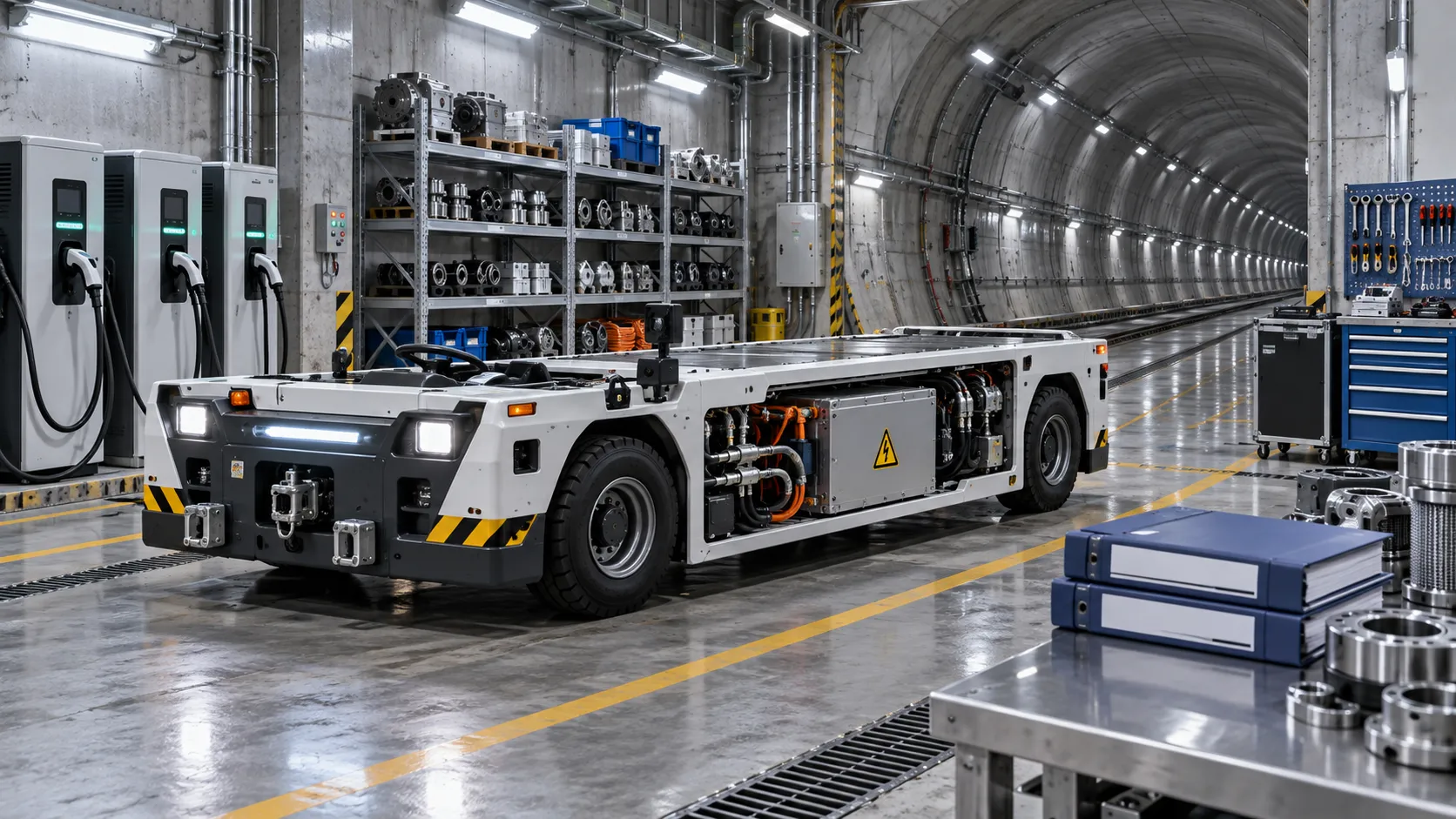
What to verify before appointing a tunneling vehicles manufacturer
Choosing a tunneling vehicles manufacturer? Verify application fit, reliability, compliance, parts support, training, and channel terms before appointing a partner.
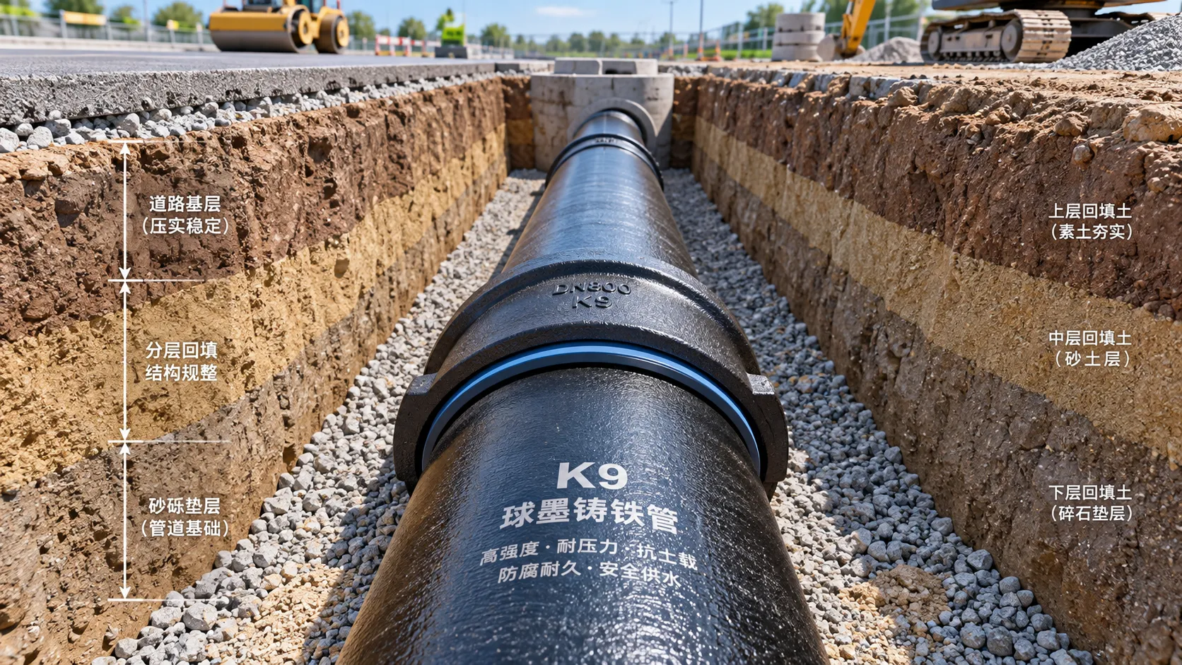
Selecting K9 Ductile Iron Pipe for Buried Water Pipeline Conditions
K9 ductile iron pipe selection for buried water pipelines: compare pressure duty, joints, soil loads, corrosion protection, and installation controls for reliable long-term performance.
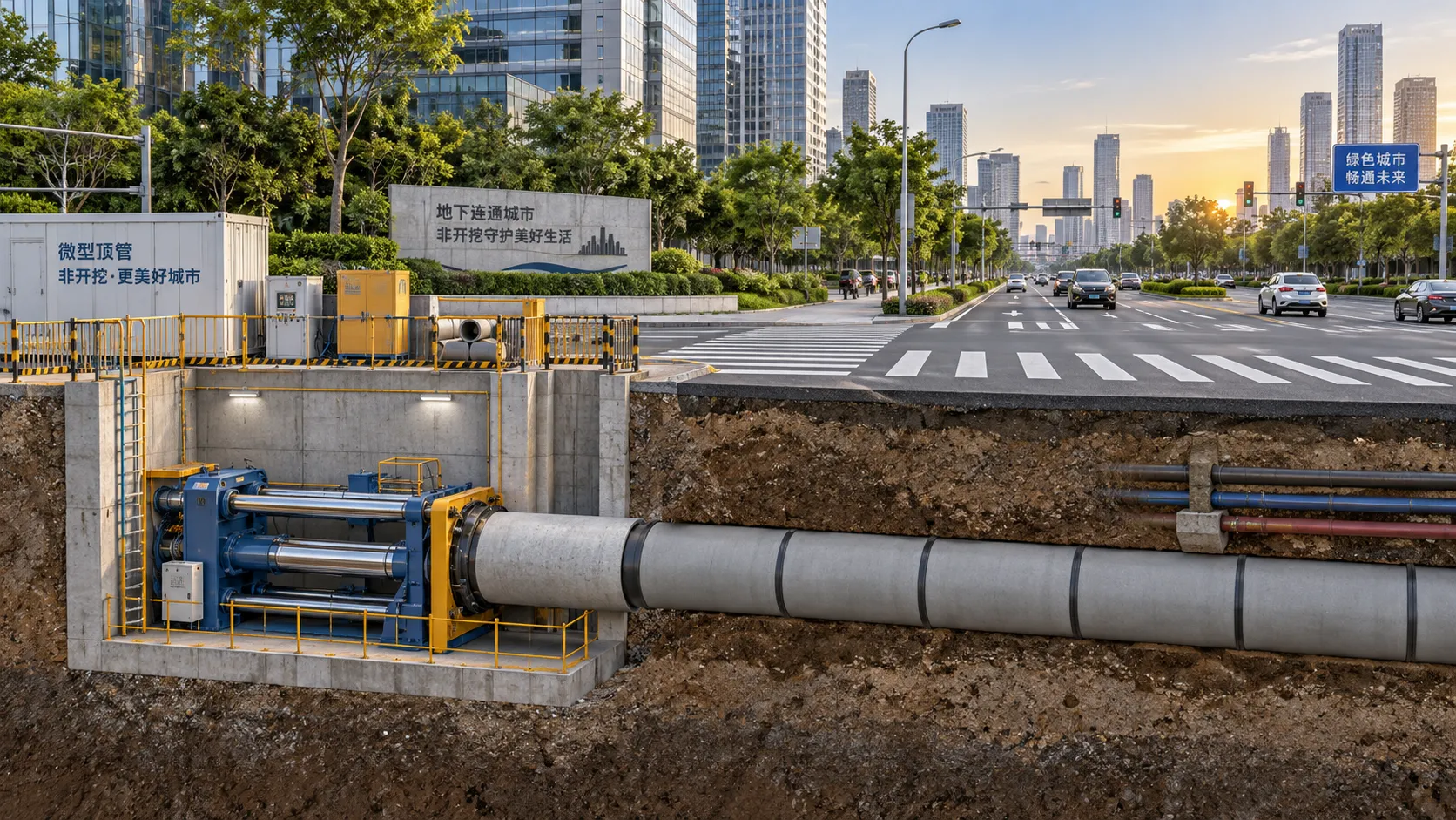
Where Trenchless Technology Delivers the Best Value in Urban Utility Projects
Trenchless Technology applications deliver high value in urban utility projects by reducing disruption, protecting critical crossings, and improving project outcomes.
Related News
- 00
0000-00
Tunnel Boring Machine Costs: Budgeting for Purchase, Operation, and Project Risk - 00
0000-00
Open-Pit Haulage Cost Analysis: How Mine Managers Can Cut Cost per Tonne - 00
0000-00
Tunnel Construction Innovations That Reduce Risk and Schedule Delays on Urban Projects - 00
0000-00
TBM Disc Cutter Design: Key Geometry and Load Factors for Hard Rock Tunnelling - 00
0000-00
Hydraulic Tipping Stability Risks in Multi-Axle Dump Special Trailers
Weekly Insights
Stay ahead with our curated technology reports delivered every Monday.