Planning Underground Communication Systems for Remote Australian Mine Sites





Remote Australian mine sites need an underground communications design that remains usable as headings extend, ground conditions change, and equipment fleets become more connected. A surface backhaul link, Wi-Fi access points, and a few radios rarely form a dependable system below ground. Rock mass, intersection geometry, mobile equipment, ventilation controls, cable damage exposure, and power interruptions all shape whether voice, tracking, telemetry, and remote-control traffic reach the places where they are needed.
Planning should begin with service requirements by underground area and operating state. A decline used for haulage has different communications demands from a production panel, refuge area, workshop, electrical substation, or development face. Treating every location as a generic coverage zone often produces a network that looks adequate on a plan but fails when vehicles turn into crosscuts, a face advances beyond the last node, or a ventilation door closes across a signal path.
Define the services before selecting the network
Underground communication systems Australia projects often combine several traffic types on one physical corridor. They should not be assigned the same availability, delay, or coverage expectation. Push-to-talk voice needs intelligible audio and rapid connection establishment. Environmental sensors transmit small packets but may need persistent paths and reliable alarm delivery. Fleet monitoring can tolerate intermittent updates in some haulage areas, while tele-remote loading, collision avoidance, and autonomous vehicle supervision may require low and predictable delay over a clearly defined operating envelope.
A useful first design document separates each service into four questions: where it must work, what happens when it is unavailable, how much data it generates, and whether traffic is stationary or moving. This exposes conflicts early. For example, a video stream from a remote loading area may consume capacity that is irrelevant to gas sensing but disruptive to voice quality if both rely on an undersized wireless segment. Likewise, tracking tags may continue reporting through a low-bandwidth system while a remote-control function has already become unsafe to operate.
The loss-of-service response belongs in this document as well. A system that loses a noncritical dashboard feed can retry later. A system supporting a machine in an active production area needs an agreed degraded state, such as stopping movement, returning to a permitted zone, or transferring control only after the connection is stable. Communications architecture and equipment behavior must be designed together; neither can safely fill in the other’s gaps.
Survey the mine as a changing radio and cable environment
Underground geometry is operationally dynamic. A straight decline can carry radio signals far beyond an intersection, whereas a sharp bend, ore pass, steel service installation, parked equipment, or partially closed door can create an abrupt shadow. Radio planning based only on tunnel length and nominal access-point range is therefore weak. The survey needs representative operating conditions: loaded and unloaded vehicles, doors in their working positions, installed services, wet surfaces, planned mesh, and the expected location of future ventilation ducting.
Rock itself is not a uniform radio barrier. Propagation changes with tunnel shape, roughness, moisture, conductive mineralisation, and the amount of metal introduced by services and machinery. A test taken in newly developed ground may not represent a production roadway later lined with cables, pipes, support hardware, and equipment. Record signal level, packet loss, round-trip delay, and roaming events along the travel path rather than relying on a single point reading. The important result is the weakest repeatable condition, not the strongest reading close to an antenna.
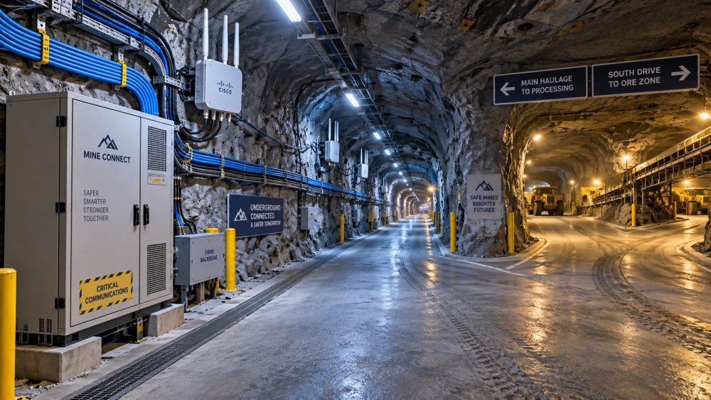
Cable infrastructure deserves the same survey discipline. Fibre provides high capacity and is well suited to backbone links, but its route must anticipate blasting, scaling, vehicle clearance, water ingress, and future extension. Fibre placed where it is easy to install today may become inaccessible or repeatedly damaged after the roadway enters regular production. Route separation, protective conduit where justified, service loops at planned extension points, and labelled splice locations reduce fault-finding time later. Excessive slack left without protection creates its own snagging and contamination risk.
In remote sites, the surface connection may also be the narrowest part of the design. Underground capacity projections are incomplete without checking the path to the mine control network, site data systems, and any external link used for support or remote supervision. Local services should continue functioning during a loss of off-site connectivity where their safety or operational purpose requires it. This calls for local control logic, retained configuration data, and clear boundaries between on-mine networks and external access.
Choose a layered topology that can move with development
A fixed fibre backbone with distribution nodes near major levels or substations is a practical base for many mines. It gives capacity for aggregation, allows segmented fault isolation, and keeps the most sensitive electronics away from the face. From that backbone, the access layer can use industrial Wi-Fi, private cellular, leaky feeder, mesh radios, wired Ethernet, or a combination. Each technology solves a different physical and operational problem; selecting one system for every heading often creates compromises that accumulate as the mine expands.
Leaky feeder remains useful where broad voice coverage along travelways is the principal requirement, particularly when a continuous radiating cable route is feasible. It is less suitable as the sole foundation for high-throughput mobile data. Wi-Fi can deliver strong local throughput but needs careful access-point spacing, channel planning, and roaming validation in moving vehicles. Private cellular can support managed mobility across larger working areas, yet tunnel geometry, distributed radio placement, core-network location, and spectrum approvals still require detailed engineering. Mesh networks can extend into temporary headings quickly, although every wireless hop consumes capacity and adds another point whose power, mounting, and alignment must be maintained.
For advancing development faces, use a planned “extension kit” rather than treating each extension as an improvisation. The kit should define approved enclosure types, fibre or copper termination methods, mounting brackets, antenna placement rules, power leads, labels, spare parts, and acceptance tests. It also needs a trigger: a measurable distance or operational boundary at which the next communications node must be installed. Waiting until users report poor coverage usually means the face has already outrun the network.
Temporary access infrastructure should be physically separated from permanent backbone assets where feasible. A development cable must tolerate frequent relocation; a production backbone needs stronger protection and controlled changes. Combining them without a boundary makes short-term work capable of disrupting a much larger area. Drawings should show not only current devices but also ownership of every patch point, enclosure, antenna, power supply, and route crossing.
Power, protection, and failure isolation determine field reliability
Communications nodes often fail because of the surrounding installation rather than a radio or switch defect. Dust, vibration, washdown water, heat, poor earthing, loose connectors, and vehicle contact are persistent hazards. Equipment enclosures need a location that remains accessible for service without sitting in a traffic strike zone or behind a temporary stockpile. Antennas mounted too low are exposed to machinery; antennas mounted behind pipework can appear correctly installed while radiating poorly into the heading.
Power architecture should identify which equipment must survive a local outage, how long it must remain functional, and what load it supports. Battery-backed power for every device is rarely justified. Prioritise communications needed for emergency coordination, alarm transmission, essential environmental monitoring, and controlled shutdown actions. Place backup supplies where they can be inspected and tested, and account for battery performance under the local underground temperature range. A central uninterruptible supply does not protect a remote node if the feeder circuit to that node trips.
Redundancy should address credible failure modes rather than simply duplicating equipment. Two access points fed by the same damaged fibre route are not independent. A ring topology may preserve backbone connectivity after a single cable break, but only if switches, routing, and physical route separation are configured to avoid a common point of failure. The same principle applies to surface gateways, fibre risers, electrical feeds, and communications rooms. Document the failure domains on the mine plan so that a blast zone, vehicle incident, or electrical isolation can be assessed against actual service loss.
Test movement, handover, and degraded states underground
Bench testing confirms that devices communicate. It does not prove that the system supports a mine workflow. Acceptance testing should include vehicles moving at expected speeds, passing intersections, stopping behind other equipment, traversing ramps, and entering the areas where critical functions will be used. Run voice calls during data transfers, observe handover between access points or cells, and compare the results with the required behavior for each service.
Latency should be viewed as a range, not an average. A low average delay can conceal short periods of high delay caused by retransmissions, roaming, congestion, or a weak return path. For supervised automation and tele-remote functions, test the delay variation, packet loss sequence, reconnection time, and action taken by the machine when communications are interrupted. Recovery needs equal attention: an automatic reconnection is not necessarily permission to resume a safety-sensitive task without confirming location, control authority, and system state.
Location systems require similar scrutiny. Tag visibility, beacon density, and map accuracy are separate matters. A tag may be detected in a level without proving which side of an intersection it occupies. Metal vehicles, stacked ore, and restricted line of sight can distort results. Where location information feeds exclusion zones or evacuation status, validate the confidence and update behavior at the specific boundaries where decisions are made.
Build maintenance into the deployment sequence
Configuration control becomes difficult when development crews relocate equipment and add extensions under schedule pressure. Every installed node should have a unique identifier linked to its physical location, network address, power source, upstream route, and intended service area. Update the as-built record immediately after field changes, not during a later documentation exercise. A topology diagram that lags the mine layout turns a minor fault into a prolonged search.
Keep spares aligned with the installed design. A collection of broadly similar radios, power supplies, connectors, and fibre patch leads can slow restoration if firmware, interfaces, or environmental ratings differ. Store suitable cleaning materials and test equipment alongside spares; underground fibre faults and contaminated connectors are not resolved by replacement hardware alone. Field procedures should distinguish between a damaged cable, an optical-loss issue, a power fault, a network configuration problem, and a radio-coverage change. These symptoms can look identical from a control screen.
Commissioning should finish with an operational handover that captures coverage maps, signal and throughput baselines, configuration backups, alarm routing, approved extension methods, and a fault escalation path. Repeat targeted surveys after major roadway changes, new production infrastructure, or introduction of connected mobile equipment. A communications system underground is an evolving utility: its reliability depends on keeping network growth synchronized with mine development, physical conditions, and the services that now rely on it.
Related News
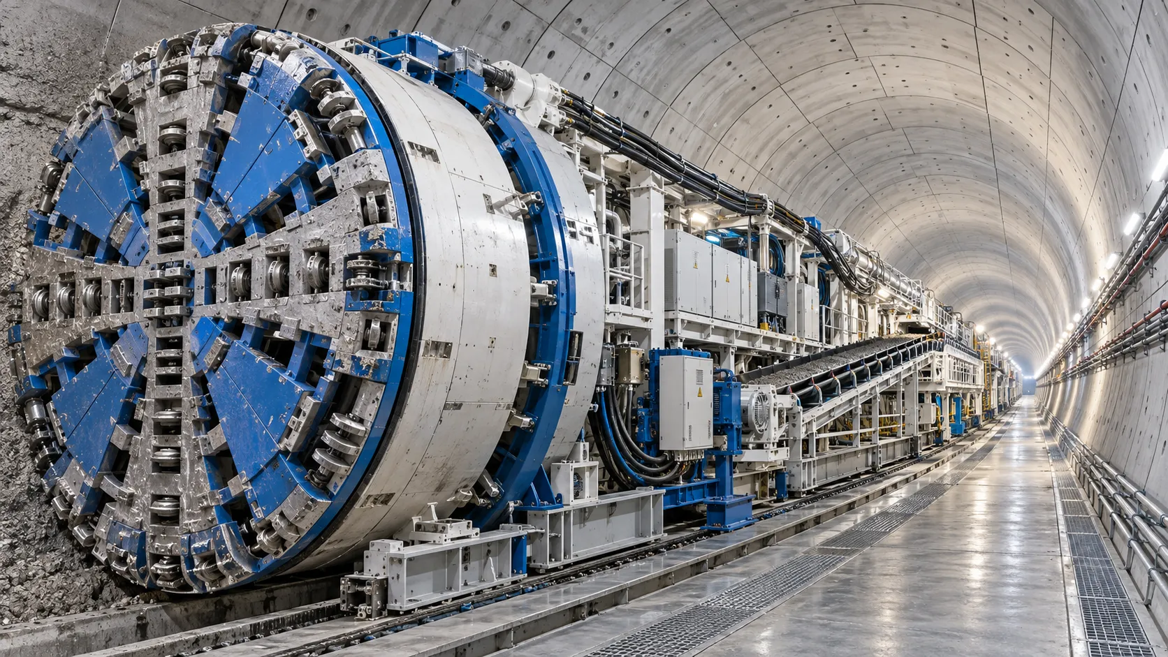
Tunnel Boring Machine Costs: Budgeting for Purchase, Operation, and Project Risk
Tunnel Boring Machines cost more than purchase price. Learn how to budget lifecycle costs, downtime, logistics, wear, and project risk for smarter TBM decisions.
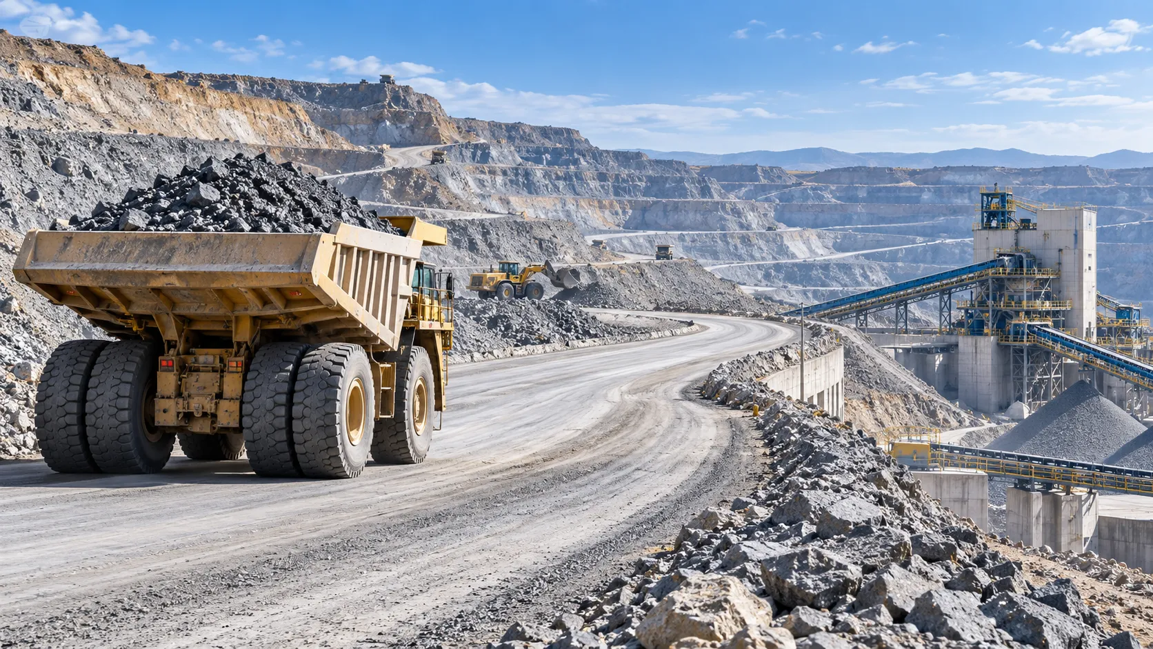
Open-Pit Haulage Cost Analysis: How Mine Managers Can Cut Cost per Tonne
Open pit haulage cost analysis: discover practical ways to reduce cost per tonne through payload control, cycle-time optimization, road performance, and smarter fleet decisions.
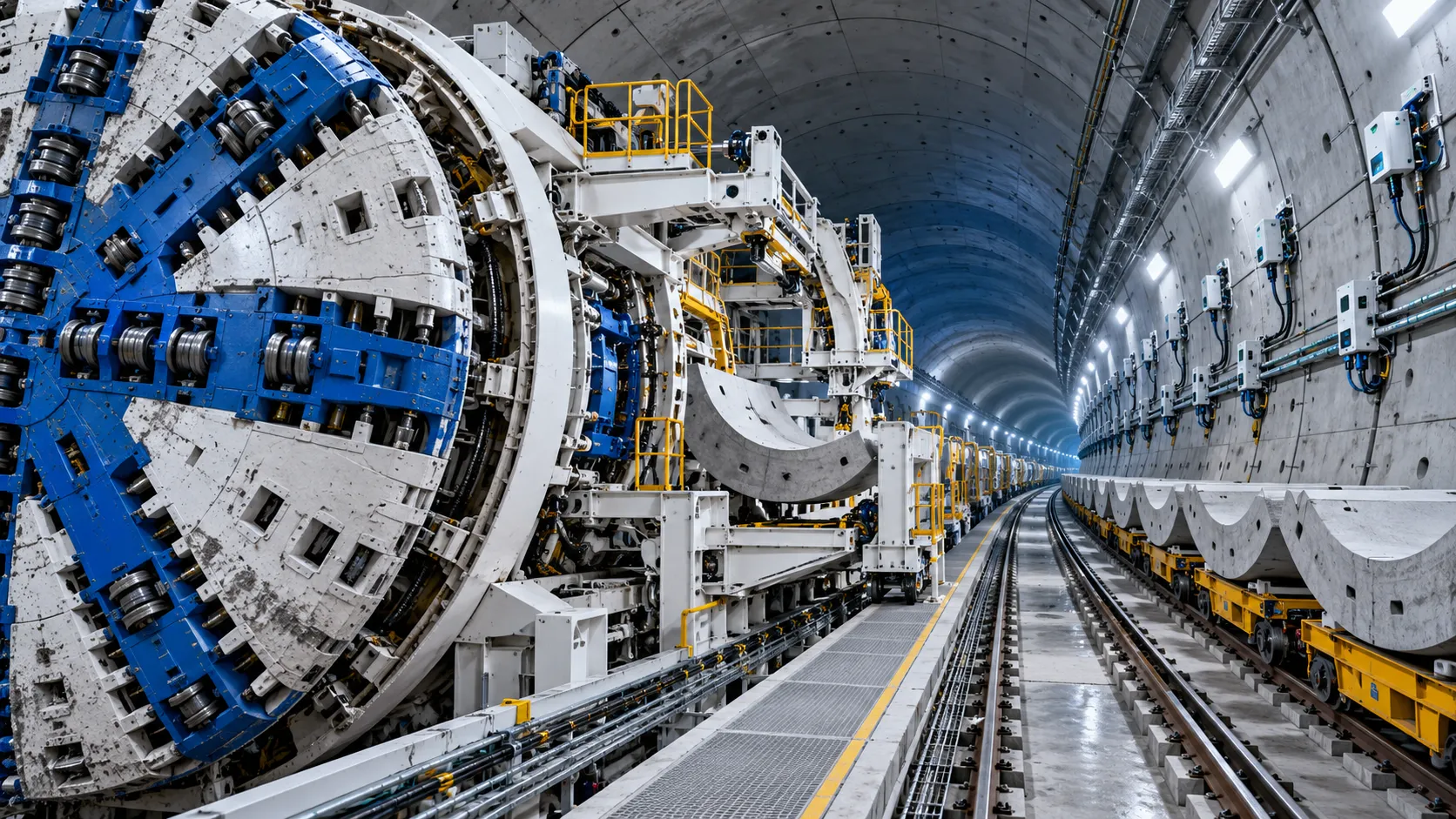
Tunnel Construction Innovations That Reduce Risk and Schedule Delays on Urban Projects
Tunnel construction innovation for urban projects: discover smarter TBMs, real-time monitoring, trenchless methods, and automation that reduce risk and protect schedules.
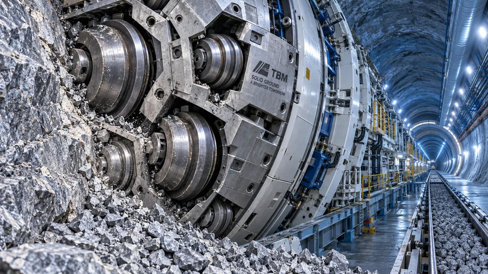
TBM Disc Cutter Design: Key Geometry and Load Factors for Hard Rock Tunnelling
TBM disc cutter design explained: explore geometry, spacing, load distribution and maintenance factors for reliable, efficient hard-rock tunnelling performance.
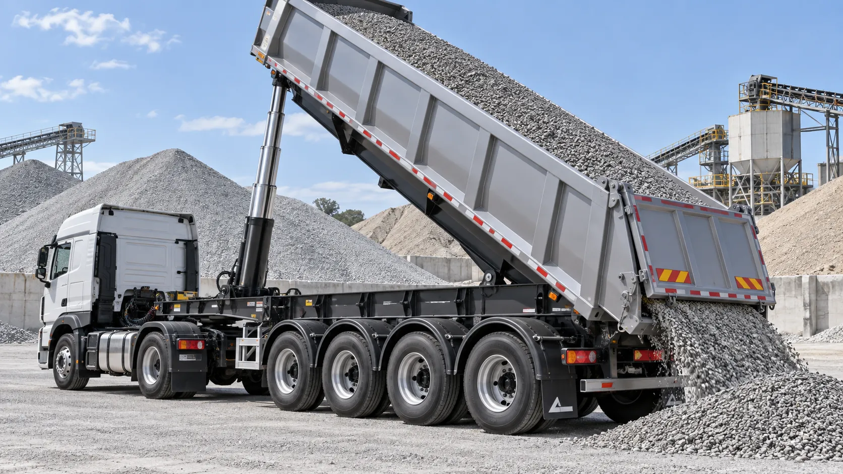
Hydraulic Tipping Stability Risks in Multi-Axle Dump Special Trailers
Dump special trailers: discover key hydraulic tipping stability risks, multi-axle load dynamics, and practical safety controls for safer, smarter bulk hauling.
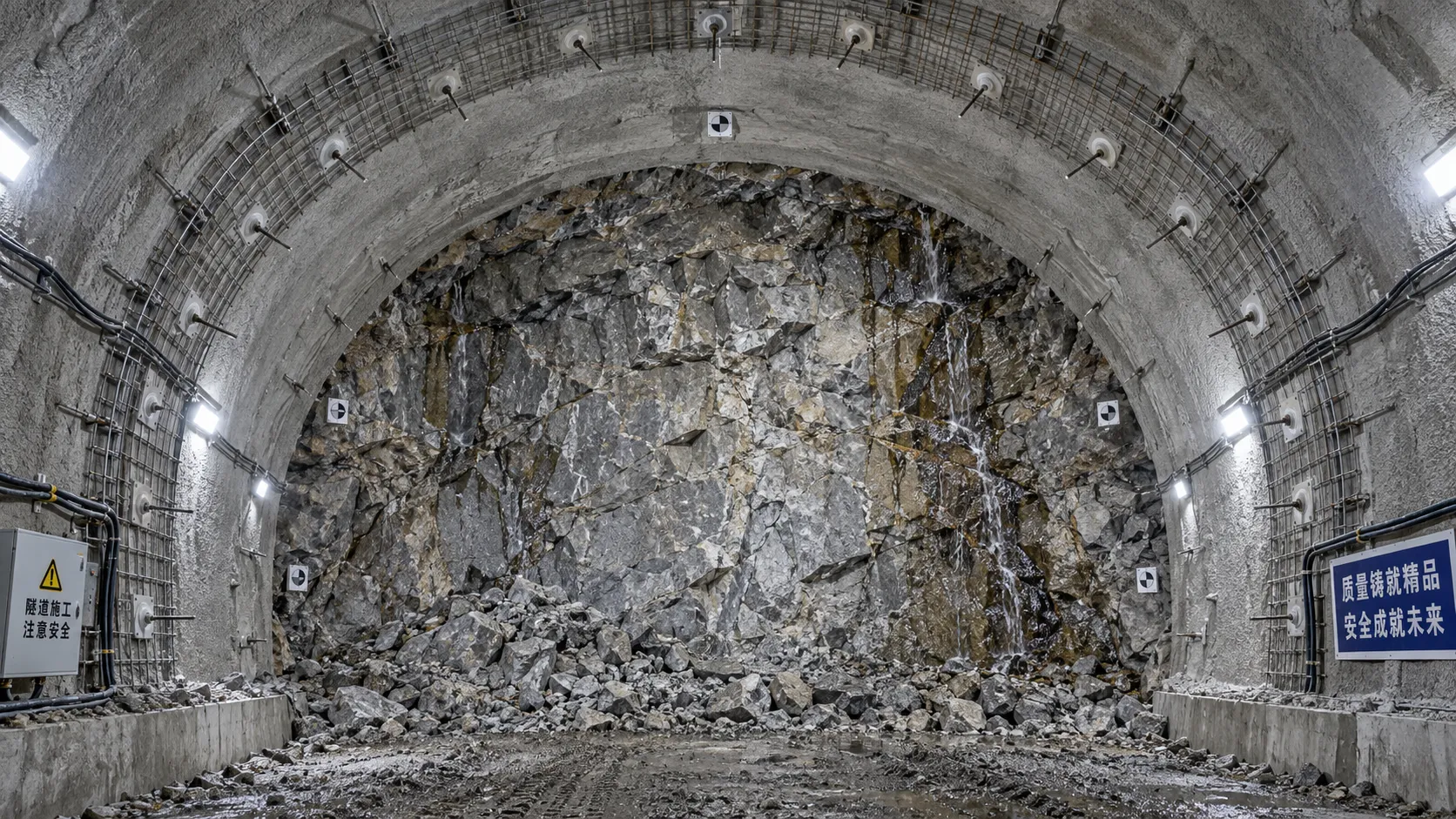
When rock reinforcement in tunnel construction must change after blasting
Rock reinforcement in tunnel construction must change when blasting reveals overbreak, weak joints, water inflow, or deformation. Discover key post-blast support decisions.
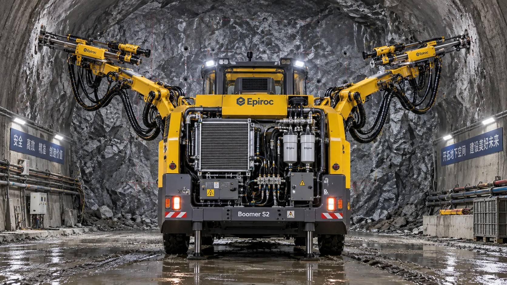
How tunnel hydraulic systems influence drill jumbo uptime underground
Tunnel hydraulic systems directly influence drill jumbo uptime. Explore how stable pressure, clean oil, cooling, and maintainable design reduce underground downtime.
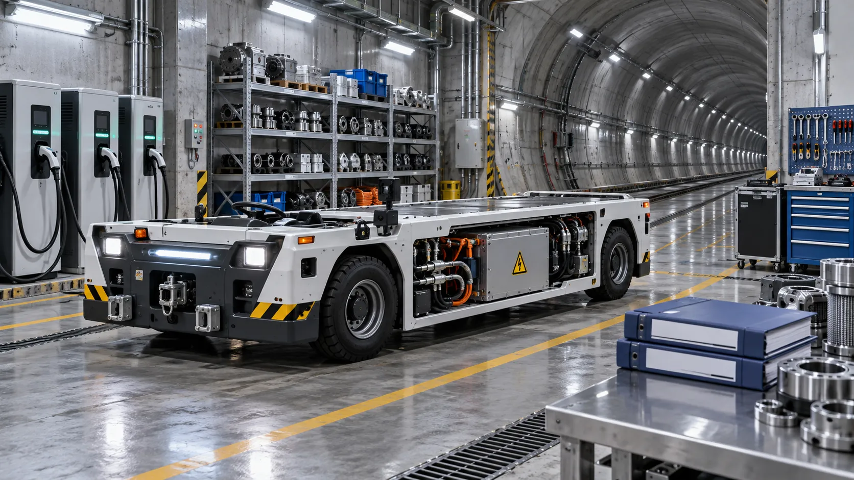
What to verify before appointing a tunneling vehicles manufacturer
Choosing a tunneling vehicles manufacturer? Verify application fit, reliability, compliance, parts support, training, and channel terms before appointing a partner.
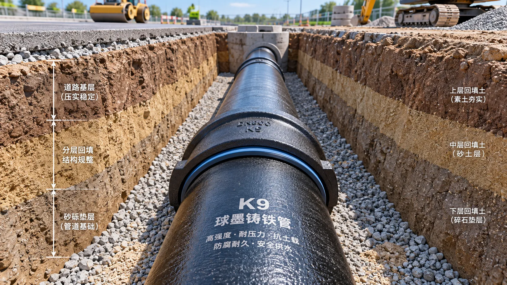
Selecting K9 Ductile Iron Pipe for Buried Water Pipeline Conditions
K9 ductile iron pipe selection for buried water pipelines: compare pressure duty, joints, soil loads, corrosion protection, and installation controls for reliable long-term performance.
Related News
- 00
0000-00
Tunnel Boring Machine Costs: Budgeting for Purchase, Operation, and Project Risk - 00
0000-00
Open-Pit Haulage Cost Analysis: How Mine Managers Can Cut Cost per Tonne - 00
0000-00
Tunnel Construction Innovations That Reduce Risk and Schedule Delays on Urban Projects - 00
0000-00
TBM Disc Cutter Design: Key Geometry and Load Factors for Hard Rock Tunnelling - 00
0000-00
Hydraulic Tipping Stability Risks in Multi-Axle Dump Special Trailers
Weekly Insights
Stay ahead with our curated technology reports delivered every Monday.